
Simatic S5 Communications Modules
Siemens SIMATIC S5 Communication Modules and CP Processors
Siemens SIMATIC S5 communication modules include CP processors and compact CPUs with communication interfaces for exchanging data with printers, operator equipment, computers and other controllers. This section covers serial links, SINEC L1, SINEC H1 and PROFIBUS-DP applications, together with CP 526 visualization boards.
Compare the complete order number, host S5 system, physical interface, protocol, firmware and configuration software. TTY, V.24/RS-232 and RS-422/RS-485 identify electrical interfaces; RK 512 and 3964(R) identify communication methods. Matching connectors alone do not establish that two devices can communicate.
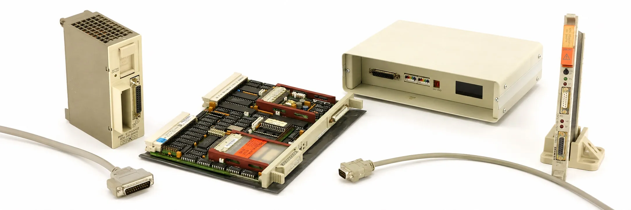
CP 521 and CP 521 SI serial communication modules
6ES5 521-8MA11 belongs to the CP 521 printer/ASCII communication group. 6ES5 521-8MA21 and 6ES5 521-8MA22 are CP 521 SI serial interface models. Printer connections, character transfer and supported operating modes depend on the hardware, firmware and application settings.
Match the baud rate, data bits, parity, stop bits and flow control as well as the cable. If message texts or driver settings are stored on a memory submodule, select replacement hardware together with preservation of the existing contents.
CP 523: serial I/O and printer connections
6ES5 523-3UA11 is a CP 523 serial I/O module for printer and serial data applications using V.24/RS-232 or 20 mA TTY. It must not be identified as CP 521 BASIC. Determine its operating mode, message memory and PLC data exchange from the CP 523 documentation.
CP 524 and CP 525 point-to-point communication
6ES5 524-3UA13 and 6ES5 524-3UA15 belong to the CP 524 serial communication processor group. 6ES5 525-3UA11 and 6ES5 525-3UA21 are CP 525 models. Check the interface submodule, installed driver, COM 525 configuration and PLC handling blocks together.
CP 524 has one serial interface, while CP 525 has two physical interfaces. Simultaneously usable ports and their functions depend on the protocol. For an existing RK 512, 3964(R) or special-driver connection, preserve the memory contents, interface number and opposite device settings as well as the hardware.
CP 526 basic boards and visualization expansions
6ES5 526-3LA01, 6ES5 526-3LA11, 6ES5 526-3LB01, 6ES5 526-3LF01, 6ES5 526-3LF11, 6ES5 526-3LG01 and 6ES5 526-3LG11 belong to the COROS CP 526 visualization basic-board group. Compare monochrome/colour video output, ventilation requirements and software generation for the complete order number.
6ES5 526-3LA21 and 6ES5 526-3LA22 are CP 526 expansion boards. They require the appropriate ventilated colour basic board and add functions such as curve and graphical displays. Match the monitor signal, keyboard, cables and application memory to the complete system arrangement.
CP 530 and the SINEC L1 network
6ES5 530-3LA11 and 6ES5 530-3LA12 are compact CP 530 variants; 6ES5 530-7LA11 and 6ES5 530-7LA12 are block-format variants. The SINEC L1 manual specifies 9,600 bit/s, with one master and up to 30 slaves. Check COM 530/SYSID settings and the BT 777 connection; distinguish CP-side TTY from bus-side RS-485.
CP 535 and SINEC H1 communication
6ES5 535-3LB11, 6ES5 535-3LB12 and 6ES5 535-3MA12 are CP 535 communication processors for SINEC H1. Assess the legacy H1 transceiver, cable and required power/interface hardware together. Preserve the existing COM 535 configuration and opposite station arrangement rather than assuming the connection behaves like a modern RJ45 PROFINET interface.
CP 544 and CP 544B serial links
6ES5 544-3UA11 is the CP 544; 6ES5 544-3UB11 the CP 544B. The family provides two data interfaces and a separate PG connection, with RK 512, 3964/3964R and open-driver configurations through COM PP. Actual speed limits depend on the fitted interface submodule and simultaneous port operation.
For a special protocol, verify the required driver, firmware and memory contents. The model designation alone does not establish that a CP 544B already contains Modbus or another special driver. A fitted interface board does not establish that the correct driver is installed.
S5-95U CPUs with SINEC L2 or a second serial interface
6ES5 095-8MB01, 6ES5 095-8MB02 and 6ES5 095-8MB03 belong to the S5-95U compact CPU family with SINEC L2. They include the controller itself. Distinguish the 8MB SINEC L2 group from 8MD DP slave and 8ME DP master versions.
6ES5 095-8MC01 is the S5-95U with a second serial interface. Check the port assignment and selectable serial communication mode together with DB1 parameters. Both ports must not be assumed to provide identical AS 511 functions in every configuration.
S5-95U PROFIBUS-DP master models
6ES5 095-8ME01, 6ES5 095-8ME02 and 6ES5 095-8ME03 belong to the S5-95U family with an integrated PROFIBUS-DP master. Back up the PLC program together with COM PROFIBUS configuration, slave addresses and I/O data areas.
For its documented 8ME01 scope, the ET 200 manual specifies up to 16 DP slaves, 9.6 kbit/s–1.5 Mbit/s and 128 input/128 output bytes. Check hardware/firmware revision, memory type and manual scope before applying those limits to another 8ME version.
TK 858 and memory submodules listed in this category
6ES5 858-0AA11 is the TK 858 telecommunications unit. Verify the line, opposite equipment, accessories and configuration against its own documentation. Direct compatibility with a modern IP network or another modem type must not be inferred from this legacy designation.
6ES5 373-0AA21 is a 16 KB EPROM and 6ES5 373-0AA81 a 128 KB EPROM memory submodule. Although listed in this category, they are memory products rather than communication processors. Check the applicable CP/carrier, programming number and contents alongside the S5 memory cards section.
Commissioning and addressing checks
When replacing a communication board, compare rack/slot compatibility, interface number, address area, jumper/DIP settings, handling blocks and startup calls. The supported method varies by module; use the addressing and port settings documented for the particular CP family.
Check cable pin assignments, active/passive TTY arrangements, RS-422/485 termination and shield connections. For serial links, match character format and protocol; for bus links, check station address, speed and termination. TX/RX activity alone does not establish that correct data reaches the application.
Test scope for used communication modules
Provide the complete model, quantity, working/faulty condition, nameplate photographs and price. Identify tested ports, fitted interface submodules, memory, fans and included cables. Power-up testing and successful data exchange with suitable opposite equipment represent different test scopes.
Editor’s note
Start by recording both device models, port names and the protocol. Select the cable by its electrical connections rather than connector shape. TTY, RS-232 and RS-485 are different interfaces; establish the signal assigned to each pin.
Before removing a working board, back up COM settings, PLC blocks and memory contents. An old EPROM may contain an essential special driver. A sound spare board with blank memory or another driver can still leave the machine unable to communicate.
Distinguish SINEC L1, SINEC L2, SINEC H1 and PROFIBUS-DP before choosing replacements. In particular, compare the master/slave role and complete network configuration before considering an exchange between 095-8MB and 095-8ME equipment.
For CP 526, check the monitor type, basic/expansion-board pairing and ventilation. Include video cables, signal format, memory and fans in diagnosis when the display fails rather than assuming the CPU is responsible.
Test transmitted and received data, error codes and reconnection after interruption, as well as LEDs. Record the exact name and version of any CP 544B special driver. Keep COM PROFIBUS configuration with the program backup for an S5-95U DP master.
Agree the fitted submodules, cables and verified functions before buying used equipment. Workshop testing is possible, with scope determined by the available hardware. All sales require an invoice; returns are not accepted. To offer S5 equipment for sale, send the model, quantity, condition, nameplate photographs and asking price to otomasyonavm@gmail.com.
OtomasyonAVM resources and PDFs
For host-system selection, see About Siemens S5 PLCs, the SIMATIC S5 main page and S5 CPU models. Use the S5 system manuals and PDF files archive for protocol, connection and configuration documents matching the complete model and edition.
Related topics
Review S5 cables and connectors, S5 memory cards, S5 interface modules, S5 central and expansion units, S5 racks and mounting frames, S5 special modules and S5 power supplies when selecting communication hardware.
Browse SIMATIC S5
+ SIMATIC S5 | Siemens S5 PLCs | S5 module groups | Used Siemens equipment | All used equipment
Siemens and external references
+ CP 521 SI Communications Processor Manual — EWA 4NEB 812 6072-02b, Edition 03; English.
+ CP 523 Serial I/O Module Manual — 6ES5 998-0DD21; EWA 4NEB 811 6044-02a; English.
+ COM 525 for CP 524 and CP 525 — Volume 1 — 6ES5 998-1DB11, Edition 08; German.
+ COROS CP 526 Communications Processor Manual — C79000-B8576-C217-01; 6AV1970-0NQ00-0AA2; English.
+ SINEC L1 Local Area Network — CP 530 Manual — 6ES5 998-7LA21; GWA 4NEB 811 0545-02d; English.
+ PMC-LS/B Communications System Manual — C79000-B8576-C743/C745-01; system communication; English.
+ CP 544 Manual — RK 512, 3964/3964R and Open Driver — 6ES5 998-2DB21; C79000-H8576-C191-01; English.
+ S5-90U/S5-95U Programmable Controller System Manual — EWA 4NEB 812 6115-02b, Edition 03; English.
+ ET 200 Distributed I/O System — S5-95U DP Master — 2806161-0002; chapters 4, 11 and 13; English.
+ Guide for Migrating SIMATIC S5 Projects to SIMATIC S7-1500 and TIA Portal — 105106251, V1.0, 04/2015; table 7-8; English.
+ WF 470 Technical Description — Memory Submodules — 6ZB5 440-0QS02; section 2.5.5; English.