
Simatic S5 Digital Output modules
Siemens SIMATIC S5 Digital Output Modules
Siemens SIMATIC S5 digital output modules transfer on/off commands from the PLC program to field equipment. Indicator lamps, interposing relays, contactor coils and solenoid valves can be controlled within the appropriate output and load ratings. This category includes DC semiconductor outputs, AC outputs, relay contact modules and special system modules.
Select the hardware using the complete 6ES5 order number, channel count, load voltage, current per channel, group current limit and S5 system compatibility. Modules sharing a 441, 451 or 458 prefix may have different connections and load ratings when their suffixes differ.
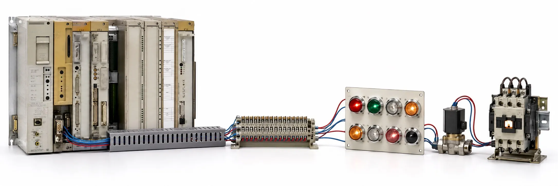
Choosing transistor, AC or relay outputs
For a DC semiconductor output, check the load voltage, current and switching polarity. P switching and M switching require different connections; S5 outputs should not all be assigned one PNP or NPN classification. For an AC semiconductor output, check operating voltage, minimum load and off-state leakage. For a relay output, contact voltage, AC/DC load type, inrush current and mechanical life matter.
Current per channel is not the module’s total current rating. Check simultaneous group loading, ambient temperature and mounting orientation separately. Galvanic isolation also does not establish that every channel is isolated from every other channel; identify whether isolation applies to individual channels or groups.
440 and compact 441 DC outputs
6ES5 440-8MA11 provides 4 × 24 V DC / 0.5 A; 6ES5 440-8MA21 and 6ES5 440-8MA22 belong to the 4 × 24 V DC / 2 A group. Match the hardware version and diagnostic features separately.
6ES5 441-8MA11 provides 8 × 24 V DC / 0.5 A. Observe the simultaneous total load limit as well as the individual channel rating.
441 rack-mounted output modules
441-4UA: 6ES5 441-4UA11 · 6ES5 441-4UA12 · 6ES5 441-4UA13 · 6ES5 441-4UA14. Other 441 models: 6ES5 441-5AA12 · 6ES5 441-7LA11 · 6ES5 441-7LA12 · 6ES5 441-7LA13.
For example, the manual specifies 441-4UA13/4UA14 as 32-channel, 24 V DC, 0.5 A output modules. These ratings do not establish direct interchangeability with every older 441 version. Check the front connector, addressing, fuses and load groups.
442, 444 and 445 output families
442: 6ES5 442-3AA11. 444: 6ES5 444-3AA11 · 6ES5 444-5AA11. 445: 6ES5 445-3AA11 · 6ES5 445-3AA12.
A logic-level output and a power output capable of driving a coil must be distinguished. Select the load using the exact model’s channel current, external supply, isolation and connector arrangement. A suffix change should not be treated merely as a cosmetic difference.
450 DC, AC and special system outputs
6ES5 450-8MB11 provides 4 × 24–60 V DC / 0.5 A; 6ES5 450-8MD11 provides 4 × 115–230 V AC / 1 A. The DC and AC modules require different load connections.
Other 450 models: 6ES5 450-3AA11 · 6ES5 450-6AA11 · 6ES5 450-6AA12. Select channel count, load current and isolation from the documentation for the actual model.
6ES5 450-8FA11 is a special digital output module for the S5-95F. Its manual describes the 450-8FAxx family as having four outputs that can provide P or M potential. Required module pairing and the safety function need the specific system arrangement.
451 rack-mounted DC outputs
451-2BA / 3AA / 3AE: 6ES5 451-2BA11 · 6ES5 451-3AA11 · 6ES5 451-3AE11. 451-5AA: 6ES5 451-5AA11 · 6ES5 451-5AA13.
451-4UA: 6ES5 451-4UA11 · 6ES5 451-4UA12 · 6ES5 451-4UA13 · 6ES5 451-4UA14. 451-7LA: 6ES5 451-7LA11 · 6ES5 451-7LA12 · 6ES5 451-7LA21.
451-7LA21 provides 32 × 24 V DC / 0.5 A outputs together with short-circuit signalling and reset connections. These auxiliary terminals must not be used as load outputs. Check isolation groups, fault signalling behaviour and total load conditions in the manual.
451 compact DC and AC outputs
6ES5 451-8MA11 provides 8 × 24 V DC / 1 A with optocoupler isolation; 6ES5 451-8MD11 provides 8 × 115–230 V AC / 0.5 A. The 451 prefix alone does not establish whether the load is DC or AC.
451 and 452 relay outputs
6ES5 451-8MR12 has 8 relay outputs, while 6ES5 452-8MR11 has 4 relay outputs. Both manual headings specify 30 V DC / 230 V AC; assess contact current and load class separately. Another MR version is 6ES5 451-8MR11.
453 DC and logic-level outputs
6ES5 453-8MA11 provides 8 × 5–24 V DC / 0.1 A. A low-current logic output should not be expected to drive a contactor or valve coil requiring more current directly.
Other 453 models: 6ES5 453-3AC11 · 6ES5 453-4UA11 · 6ES5 453-4UA12 · 6ES5 453-7LA11. Determine load voltage, channel current and supply reference for the complete model.
454 DC output models
454-2BA / 4UA / 5AA: 6ES5 454-2BA11 · 6ES5 454-4UA11 · 6ES5 454-4UA12 · 6ES5 454-4UA13 · 6ES5 454-4UA14 · 6ES5 454-5AA11.
454-7LA / 7LB: 6ES5 454-7LA11 · 6ES5 454-7LA12 · 6ES5 454-7LB11. Channel count and load capacity can differ within the family. Do not select a replacement using the 454 number alone. Check supply groups, fuses and simultaneous load conditions together.
455, 456 and 457 output models
455 models: 6ES5 455-6AA12 · 6ES5 455-7LA11. 456 models: 6ES5 456-4UA11 · 6ES5 456-4UA12 · 6ES5 456-6AA12 · 6ES5 456-7LA11 · 6ES5 456-7LB11. For AC output selection, check rated voltage, permissible operating range, minimum load and off-state behaviour.
Standard 457 models: 6ES5 457-4UA12 · 6ES5 457-7LA11. Their load and connection ratings must not be applied to the Ex model below.
458 relay contact output modules
458-4U models: 6ES5 458-4UA11 · 6ES5 458-4UA12 · 6ES5 458-4UC11. 458-7L models: 6ES5 458-7LA11 · 6ES5 458-7LB11 · 6ES5 458-7LC11.
A contact’s highest current rating does not apply to every load. For example, the 458-7LB11 manual specifies a switching capacity of 5 A for a resistive load at 250 V AC and 0.5 A for an inductive load at 30 V DC. A “5 A relay” description alone is insufficient without voltage and load type.
457-8EA12 Ex digital output module
6ES5 457-8EA12 is a four-channel Ex output module for intrinsically safe field circuits. The manufacturer specifies a logic-1 output voltage of 7 V DC maximum and a rated output current of 2 mA. The diagram’s 9 V marking should not be treated as a standard 9 V power-output rating. Select field equipment, the Ex bus unit and circuit conditions using the applicable documentation.
410, 415 and 417 legacy S5 output hardware
410: 6ES5 410-0AA12 · 6ES5 410-0AA41 · 6ES5 410-7AA11 · 6ES5 410-7FA11. 415: 6ES5 415-7AA11 · 6ES5 415-7AA31 · 6ES5 415-7AB11 · 6ES5 415-7AB21. 417: 6ES5 417-7AA21.
Identify the CPU family, host system, load supply and front connector connections using the complete order number. Physical resemblance to another S5 board does not establish that it can be installed as a direct replacement.
Addressing, power supply and loaded testing
Addressing example: a 32-output module assigned starting byte 8 and using four consecutive bytes would be described as Q 8.0–Q 11.7 in English STEP 5 notation. This illustrates address numbering only. The actual starting address depends on slot or switch settings and the CPU system. A slot number is not universally the output byte address across S5 systems.
If an output is missing, check the program command together with the CPU operating state, any BASP/output inhibit, load supply, fuse and common connection. A semiconductor output may show voltage on an unloaded multimeter test yet fail to deliver current under load. Use a suitable test load.
For inductive loads such as contactors and valves, consider the module’s internal protection together with suppression fitted at the load. A DC coil diode, RC network and varistor require different connections. Select suppression for the coil and manufacturer instructions, including its effect on release time.
Used equipment purchasing and selling
For a quotation, provide the complete model, quantity, working or faulty condition, label photograph and asking price. Send details of equipment you wish to sell to otomasyonavm@gmail.com. Sales require an invoice; used equipment is sold without returns. Workshop testing with an appropriate system and test load may be arranged.
Editor's Note
An unsuitable load can damage a healthy output module. Establish the coil voltage, running current and inrush current first, then choose the module. Do not connect an unidentified load by guesswork.
An output LED alone is not proof of a working channel. Check voltage and current with a suitable load. A relay may click despite damaged or resistive contacts, and a semiconductor output can appear healthy with no load connected.
If every output in one group is missing, check the common supply, group fuse and terminal connections before replacing the board. One broken common connection can resemble several failed channels.
Compare the complete suffix, front connector and address settings when choosing a spare. Photograph the existing wiring and record wire numbers and jumper positions. Similar housings do not establish matching connections.
One working channel does not prove the condition of the whole board. Test the required channels and load groups separately, then observe temperature and stability under simultaneous load. Correct the load problem before fitting a replacement, or the failure may recur.
OtomasyonAVM Resources and PDF Manuals
For system selection, review the SIMATIC S5 CPU families and S5 module categories. Compare specifications with the manual and edition covering the complete device code.
+ Shared Siemens SIMATIC S5 PDF archive
+ S5-100U Ex I/O manual — English
+ S5-115U system manual — English
+ S5-135U/155U system manual — English
Related Topics
S5 digital input modules · S5 digital input/output modules · S5 power supplies · S5 cables and connectors · S5 interface modules
Browse SIMATIC S5
Parent S5 module category · SIMATIC S5 CPU options · Siemens S5 PLCs · Used Siemens automation equipment
Siemens and External References
+ Siemens — S5-100U System Manual (English)
+ Siemens — ET 100U Distributed I/Os (English)
+ Siemens — S5-115U System Manual (English)
+ Siemens — S5-135U/155U System Manual (English)