
Position control sensors
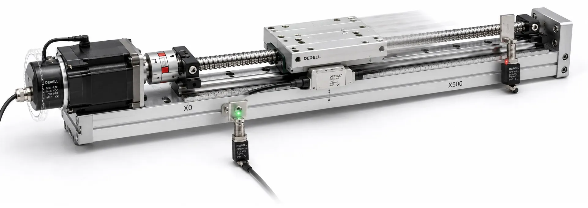
Position control sensors: types, model examples and selection
Position control sensors are sensors that convert a component's position, displacement or arrival at a defined point into electrical information. They can track a shaft angle, a machine table's movement or a product on a conveyor. In industrial automation, selection starts by defining the information required.
In a position control system, the sensor reports actual position, the controller compares it with the target, and the drive adjusts movement. A suitable PLC or motion controller may form part of this system. A sensor's ability to measure position does not, by itself, guarantee accurate positioning of the whole machine.
Point detection and continuous position measurement
Point detection answers “is the part here?” A proximity sensor, an inductive sensor for a metal target or a capacitive sensor for suitable materials changes its output at a defined detection condition. A limit switch generally reports a position point through mechanical contact.
Continuous position measurement answers “how many millimetres has the part moved?” or “what is the shaft angle?” Encoders, LVDTs and distance sensors with measurement capability can serve this purpose. A presence/absence output does not automatically provide a position value in millimetres. A reference sensor can nevertheless help establish the starting point of an axis that also has continuous measurement.
Rotary encoders: incremental and absolute feedback
A rotary encoder converts shaft movement into electrical signals. An incremental encoder generates pulses as it moves. The phase relationship between A and B channels allows direction to be determined; a Z channel, when provided, supplies an index mark. The controller evaluates these signals using suitable edge counting and a high-speed counter input. Referencing may be required after power loss, depending on the machine.
An absolute encoder provides a defined value for each position within its measurement range. A single-turn device reports angle within one revolution; a multi-turn device also reports the revolution count within its supported range. Tracking movement without power depends on the device's construction. An absolute encoder does not automatically eliminate every machine reference or calibration procedure.
Speed can also be calculated from encoder feedback, but measuring RPM and tracking angular position are different evaluations. Mechanical options include a hollow-shaft encoder or a suitable coupling arrangement. Check shaft diameter, misalignment and mechanical load limits together.
Linear encoders: measuring movement directly
A linear encoder tracks straight-line movement using a scale and readhead. Optical systems read an optically encoded scale; magnetic systems read a suitable magnetic scale. When comparing optical and magnetic encoders, assess accuracy, installation clearance, contamination and environmental conditions for the actual model. Both technologies are available in different performance classes.
An encoder on the motor shaft measures shaft movement. A linear encoder mounted to the load can measure load movement directly. Screw backlash, belt stretch or coupling slip can cause the two readings to differ. Select encoder accessories and mounting parts to preserve the mechanical integrity of the measurement chain.
Position measurement with potentiometers and LVDTs
A position potentiometer changes the position of a moving wiper along a resistive track. With suitable wiring, it acts as a voltage divider and produces a position-dependent voltage. Rotary and linear versions are available. Check mechanical life, contact wear, travel, linearity and loading by the measurement input. Not every adjustment potentiometer is suitable for industrial position feedback.
An LVDT, or linear variable differential transformer, operates through a moving core that changes magnetic coupling between coils. A basic AC design has one primary and two secondary windings; their differential signal varies with displacement. The device's construction determines its excitation and signal-conditioning requirements. A bare AC LVDT output cannot be connected directly to an ordinary PLC analog input.
A conditioned measurement device can provide a suitable analog signal. With interfaces such as 0–10 V and 4–20 mA, match the measurement range to the output range. For a 4–20 mA output configured for 0–100 mm, 12 mA represents 50 mm under ideal linear scaling. Verify the actual relationship through configuration and calibration.
Hall and capacitive measurement methods
A Hall sensor converts a magnetic field into electrical information. Position measurement requires consideration of magnet geometry, field orientation and sensor distance. Hall-effect encoder arrangements can provide angular position feedback. Hall sensors and reed switches have different output structures; magnetic switching and continuous measurement are separate functions.
A capacitive displacement sensor measures changes in capacitance between a probe and a suitable target to determine distance or displacement. Precision systems require attention to target material, grounding, surface geometry and probe clearance. Such a device should not be treated as equivalent to an ordinary capacitive proximity switch. A capacitive encoder is another application that reads encoded position through capacitive sensing.
Ultrasonic, laser and fibre-optic sensing
An ultrasonic sensor using the echo method determines distance from the sound pulse's round-trip time. The blind zone, target angle, sound-absorbing surfaces and temperature can affect the result. One application may require switching alone, while another needs continuous distance feedback; select the appropriate output capability.
A laser sensor belongs to a family of light-based sensors. Continuous measurement requires a suitable distance-measuring model; not every laser sensor supplies a distance value. Methods such as triangulation and time of flight have different range and surface requirements. Consider reflectivity, transparency, spot size and the actual target dimensions.
A fibre-optic sensor arrangement carries light to the sensing point through optical fibres. It can suit confined spaces and small-part applications. Common fibre amplifiers provide photoelectric detection rather than automatically measuring continuous position. Assess the sensing fibre and electronic amplifier's environmental requirements separately. Using fibre does not make the whole system immune to electromagnetic interference.
Which sensor families do these model examples belong to?
These examples help identify product families. The complete order code determines output, measurement range, resolution and mechanical connection options. Models within the same series are not necessarily interchangeable.
| Model or series | Sensor family | Selection consideration |
|---|---|---|
| OMRON E6B2-CWZ6C | Incremental rotary encoder, NPN open-collector output | Pulse count and complete order code |
| HEIDENHAIN ROD 420 | Incremental rotary encoder | Should not be classified as an absolute encoder |
| Baumer MAGRES EAM580 | Magnetic absolute rotary encoder family | Not a magnetic-strip linear encoder |
| Renishaw TONiC | Optical incremental encoder system | Compatible scale, readhead and interface for linear use |
| Bourns 3590 | Precision multi-turn rotary potentiometer | Mechanical travel, resistance and service-life requirements |
| TE Connectivity MEAS MHR | Miniature LVDT family | Excitation, stroke and conditioning circuit |
| Lion Precision CPL190/CPL290 | Capacitive displacement measurement system | Probe, target and calibrated range |
| Banner DF-G1 | Fibre-optic amplifier family | Detection with suitable fibres; continuous position output should not be assumed |
Understanding resolution, accuracy and speed
Resolution describes the smallest distinguishable step; accuracy describes closeness to the true value; repeatability describes consistency when returning to the same position under the same conditions. High resolution does not guarantee an equivalent level of mechanical accuracy.
Suppose an encoder produces 1000 A-channel pulses per revolution. Counting all four edges of the A and B channels gives 4000 counts per revolution. If the encoder is connected directly to a screw with 5 mm travel per revolution, the theoretical increment is 5 / 4000 = 0.00125 mm per count. Backlash, compliance and installation errors are outside that calculation.
At 1500 RPM, the same encoder's A-channel pulse frequency is 1000 × 1500 / 60 = 25,000 Hz. Four-edge decoding requires the counter to process 100,000 counts/s. Assess counting frequency alongside the sensor's electrical limits and the input's permitted channel frequency. Filtering, cabling and signal quality also matter.
Output signals and controller compatibility
The measurement output must match the connected input module. For point detection, PNP/NPN describes the electrical output arrangement and NO/NC describes switching behaviour. For encoders, check TTL/HTL signal levels, line-driver outputs and differential signalling. These are not interchangeable connection labels.
For analog interfaces, check scaling. For pulse interfaces, check counting, direction and frequency. For absolute digital interfaces, check communication compatibility. Read supply voltage, pin assignment, common connection and cable limits for the complete product code.
Installation and commissioning: compare feedback with actual movement
Assess the IP protection rating, temperature, vibration and chemical resistance together. Select cables or connectors for the movement conditions. Near power wiring, follow the manufacturer's guidance on electromagnetic interference. Match the measurement range to the mechanical travel limits.
Verify readings at two or more known positions. Check direction, zero point, scaling and behaviour after power is restored. When feedback serves a servo motor axis, assess the mechanics and control settings as well. In PID position control, measurement delay and motion dynamics affect tuning.