
what is Motor flux braking?
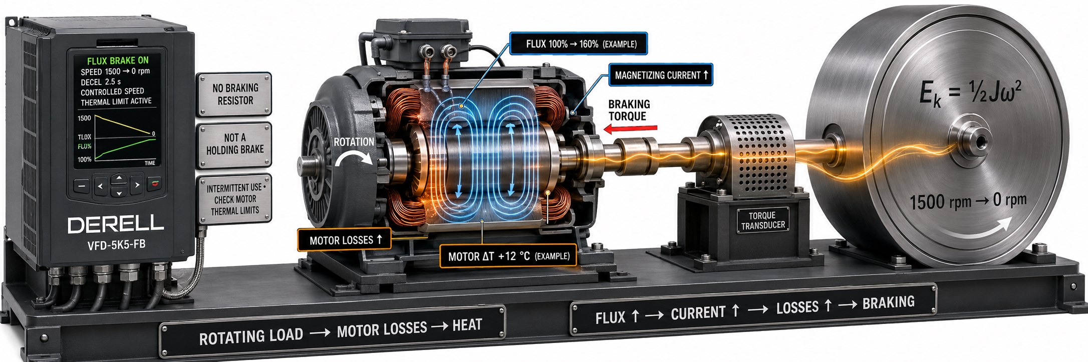
Motor flux braking helps a compatible variable frequency drive slow a load by increasing the motor's magnetization. Part of the motion energy is dissipated as heat inside the motor. The function itself does not recover energy to the mains. Its usefulness depends on the stopping duty and the motor's ability to handle the extra heat.
What changes during a flux-braking stop?
The drive raises magnetic flux and the associated magnetizing current. Additional motor losses provide another route for removing energy from the rotating system, helping increase the available braking torque. Controlled deceleration remains subject to the motor, drive and load limits.
Direct torque control (DTC) can manage flux and torque directly, but DTC is not a universal requirement for flux braking. The function is also found in suitable vector-controlled drives. A reference to flux vector control alone does not establish that a particular drive offers flux braking; check its function description.
Follow the energy to distinguish braking methods
DC injection braking applies direct current to the motor windings. DC braking uses a different control approach from flux braking, which can retain motor control and allow a transition back to acceleration.
Resistor braking sends energy from the drive's DC link through a braking chopper to a braking resistor. Regenerative braking to the mains uses suitable power hardware to return regenerated energy to the supply. Flux braking puts the additional thermal burden inside the motor.
Why motor size and resistance matter
In smaller motors, winding resistance can have a relatively greater effect at rated current. The elementary resistive-loss relationship is P = I² × R: at a fixed current, a higher resistance produces more heat. “Higher resistance means less flux-braking power” is therefore not a valid general rule. The usable result also depends on current limits, speed, motor construction and thermal capacity. A small motor is not automatically suitable for every stopping duty.
A worked example: Stop time versus stop frequency
Assume a total inertia referred to the motor shaft of 0.08 kg·m² at 1,500 rpm. Using E = ½ × J × ω², with ω = 2π × n / 60, the stored rotational energy is approximately 987 joules.
Removing that energy in two seconds requires an average of roughly 494 W. Spreading the stop over ten seconds reduces the average to about 99 W. These figures describe energy removal, not a drive rating or a guaranteed flux-braking capability. The calculation excludes friction, external load work and other losses. It shows why changing the deceleration ramp can change the braking demand without changing the motor.
A longer stop does not change the initial stored energy; it changes the rate of removal. Repeat this example stop every ten seconds and the energy per cycle corresponds to about 99 W averaged over the cycle. Repeat it once per minute and that figure becomes about 16 W. Neither number is the motor's actual additional heating. They illustrate why one successful stop cannot validate a repetitive duty.
What to check before enabling it
Start with accurate motor nameplate data, especially rated current, and perform the specified motor identification or auto-tuning procedure where required. Check the acceleration and deceleration settings alongside the selected stop mode. A coast stop is not an actively controlled ramp stop.
Keep current and temperature limits in place. Relaxing current limiting or motor overload protection to force a shorter stop is not a sound commissioning method. A suitable winding PTC sensor can provide temperature monitoring. Assess a representative sequence of stops, not just the first stop from a cold motor.
Braking levels are product-specific. For example, the ABB ACS580 Rev E manual describes 97.05 Flux braking with disabled, moderate and full selections. Do not carry that parameter number across to another drive. Full braking can cause substantially more heating in cyclic service.