
What is crane vfd devices?
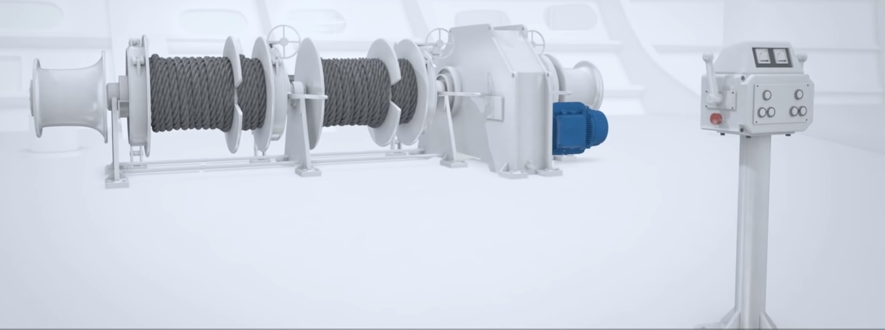
Controlled lifting, lowering and travel
Hello, a crane drive is a variable frequency drive that controls the speed and torque of hoist, trolley and bridge motors. Models suitable for crane applications may add mechanical brake management, low-speed control and controlled load pickup to standard motor control. These capabilities vary between products; crane drives must be assessed against the motion and duty cycle involved.
How does it control the motor?
The drive regulates motor speed by controlling its supply frequency and voltage. Vector control uses a motor model and, where fitted, feedback to provide more controlled torque at low speed. Torque control and speed control are different functions: the force required by the load and the desired movement speed must be considered together.
Encoder feedback may be used for precise movement at very low speed or actual-speed monitoring. A drive's ability to run without an encoder does not make it suitable for every hoist. Motor type, load behavior and the manufacturer's requirements for lifting applications all matter.
Why are hoisting and travel different?
Gravity continues to pull the load downward on a hoist axis. Starting therefore requires load pickup without rollback, lowering requires speed control, and stopping requires the load to be secured by the mechanical brake. Trolley and bridge motions place greater emphasis on inertia, speed transitions and load sway. Two motors with the same power rating may require different drive settings when performing different motions.
Mechanical braking and torque proving
During a normal start, the motor must establish enough torque to take the load before the brake releases. The aim is to prepare holding torque, rather than to rotate the motor beforehand. During a normal stop, decelerate under control and confirm that the brake is holding the load before removing motor torque. Assess braking torque, release/application times and brake feedback together.
Some crane software provides torque proving, brake release/application monitoring and brake-slip detection. These are not standard features of every inverter. Select the mechanical holding brake with power failures and faults in mind; the motor's ability to produce holding torque does not make it a replacement for the mechanical brake.
Editor's note: Safe Torque Off, or STO, prevents the motor from generating torque. It cannot hold the load by itself, does not necessarily control the brake coil and does not provide electrical isolation. Safe brake actuation may require a separate function or an appropriate control arrangement. Define emergency stopping by considering the brake and drive together.
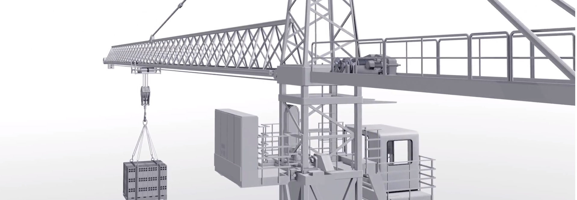
Energy generated during lowering
When a descending load drives the motor, the motor can operate as a generator. Energy returning to the drive's DC link can be converted to heat through a suitable brake chopper and braking resistor, or returned to the mains through an appropriate regenerative system. A resistor is therefore not mandatory in every crane configuration, and not every inverter can recover energy to the supply.
The braking resistor's resistance, peak power capability, energy per cycle and average power must suit the lowering duty. The financial benefit of regeneration also depends on load, lowering height, cycle frequency and system losses. A braking resistor does not replace the mechanical holding brake.
Control functions for crane applications
Precision positioning and multiple speeds: Low speed can assist load placement, while higher speeds may suit appropriate travel distances. An S-curve can smooth speed transitions, but it is not equivalent to dedicated anti-sway software. Anti-sway control also cannot guarantee complete elimination of sway under every condition.
Load sharing and synchronization: Motors working together may need speed/torque sharing, while paired hoists may require coordinated movement. A master/follower function alone does not create a safe tandem lifting system; the mechanical arrangement, feedback and monitoring must be designed together.
Load-dependent speed optimization: Some systems allow faster operation with lighter loads. This must remain within the permitted limits of the motor, brake, gearbox and crane. An unloaded hook does not justify unrestricted speed increases.
Monitoring load and travel limits
Assess load measurement and overload protection separately from motor current limiting. Motor current is not a direct, universally reliable measurement of lifting capacity. Arrange limit switches, slowdown zones and any required safety-related final limits appropriately. A software position limit is not automatically a safety limit.
An inverter alone cannot arrest a load following a mechanical failure such as rope breakage. A stop command is insufficient when the motor no longer controls the load. Specify the necessary mechanical and electrical protective measures according to the crane's construction and risk assessment.
Operator controls, monitoring and practical benefits
Direction and speed commands can come from a radio remote control or wired pendant. Integration with PLCs and automation systems can provide communication, status monitoring and fault records. Clearly define stopping and restart behavior following signal loss; remote access alone is not a safe maintenance method.
A correctly selected and commissioned system can reduce mechanical shocks, improve precise load placement and decrease brake wear. However, neither a fixed energy-saving percentage nor a “30–40 times longer brake life” claim applies universally. Benefits depend on the duty cycle, mechanical arrangement, brake use and settings.
When comparing products, consider the motor nameplate, motion type, maximum load, duty cycle and brake details together. For selection guidance, see what to consider when buying a crane drive.
Related products: Crane drives, braking resistors, servo and motion control systems, switchgear.