
About Mitsubishi Alpha smart relay
From relay panels to compact programmable control
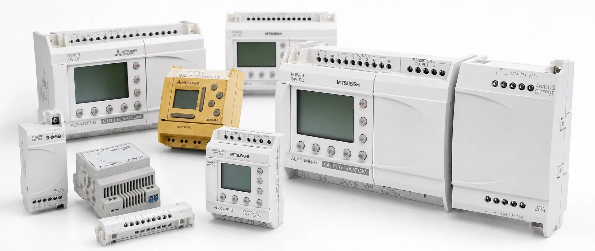
Hello, the Mitsubishi Electric ALPHA family consists of smart relays for applications that appear small enough for a few relays, but become complicated once timing, counting and operating schedules are added. Mitsubishi’s description, Simple Application Controller, explains its purpose: to bring small control tasks into an understandable program. ALPHA2 is the later generation of this approach, offering greater program capacity and additional functions.
An ALPHA2 is more capable than a simple electronic relay, while remaining subject to the limits of its compact controller class. It reads inputs, evaluates the control program and operates outputs. Its processing, expansion and communication capabilities should therefore be assessed against the actual application. Understanding the differences between smart relays and PLCs is useful when designing a new system or replacing an existing programmable controller.
The original need: moving control logic from wiring into software
Traditional control panels used separate auxiliary relays, timers, counters and time switches. A ventilation system that followed a weekly schedule, continued running after the lighting switched off and displayed a fault could require several components. Changing the operating rules could mean altering the wiring and rearranging the panel.
Compact programmable logic modules became an established product category during the second half of the 1990s. Siemens’ official history dates the launch of its LOGO! module to 1996 and describes the replacement of conventional relay, timer and counter functions. This provides useful industry context. It is not the launch date of Mitsubishi ALPHA.
The change did not eliminate the power circuit. Contactors, overload protection and field wiring remained necessary. What changed was the decision-making part of the control system: when to start, how long to wait and when to stop could increasingly be defined in software rather than through numerous physical connections.
The 1999 record: the original ALPHA generation
Mitsubishi Electric’s JY992D76601 programming manual, revision C, dated October 1999, documents the original ALPHA. It specifies 64 function blocks or 1,500 bytes of program capacity and a display with four lines of ten characters. It also describes front-panel programming and the AL-PCS/WIN-E PC software.
The practical change was that a small operating rule could be implemented within one controller. A light remaining on for twenty seconds after a pushbutton was released, for example, could be built from logic and delay functions. This provided control behaviour that could be changed through programming without requiring a larger automation platform.
Editor’s note: Keep the two generations separate. 64 blocks and a 4×10 display describe the original ALPHA; 200 blocks and a 4×12 display describe ALPHA2. Check the complete model number on the rating label.
The early 2000s: the ALPHA2 development
The April 2002 revision A of JY992D97101 establishes that ALPHA2 was documented by that date. This is a verified manual date, rather than a single launch date applicable to every market. ALPHA2 increases capacity to 200 function blocks or 5,000 bytes. Both limits matter: the memory required by the selected blocks also determines whether a program fits.
A display with four lines of twelve characters and eight front-panel keys provides a small local operator interface. It can show operating messages, timer values and counter values. It should be understood as a means of checking status and adjusting suitable parameters locally; its capabilities are much smaller than those of a full operator terminal.
2008–2009: a more developed programming and training environment
The March 2008 revision F programming manual covers functions extending beyond basic switching, including comparison, calculation, display management and timing. Mitsubishi’s separate beginner’s manual dated 11 December 2009 documents the training material available for learning and applying the controller. These dates mark developments in documentation and application support; they do not, by themselves, identify new hardware generations.
The ALPHA family uses function block diagrams. Inputs connect to functions such as AND, OR, delay, counting and comparison, and their results control outputs. In the general FBD approach, the connecting lines represent information and logic flow rather than electrical power. Drawing blocks is only useful when their conditions and interactions are understood.
Knowledge of Ladder diagrams can help with the underlying logic, but an ALPHA project should not be treated as a directly interchangeable Ladder program from another PLC. Similarly, an FBD-style interface does not establish that ALPHA is programmed with CODESYS or can execute any IEC program. The programming environment, project format and target-device compatibility are separate issues.
The 2010s: building a small control system around one controller
Mitsubishi Electric’s March 2010 ALPHA brochure describes applications including pumps, tank level, pressure monitoring, ventilation and lighting, alongside analogue adapters, expansion options and communication accessories. Its historical significance is the combination of measurement, local indication and remote notification around a compact controller.
The brochure’s GSM/SMS and AS-i options also reflect the communication arrangements of that period. They do not imply that every base unit contains an internet connection. When refurbishing a GSM installation, check the modem, operator service and support for the mobile network it uses. A feature listed in an old brochure does not guarantee that the entire communication chain remains usable today.
Model numbers, input/output counts and expansion limits
The AL2-10MR provides six inputs and four relay outputs; the AL2-14MR provides eight inputs and six relay outputs; and the AL2-24MR provides fifteen inputs and nine relay outputs. The suffix -A indicates a 100–240 V AC supply, while -D indicates 24 V DC. Always check the field-input specifications as well as the supply rating.
The AL2-10MR is not expandable. Compatible 14-point and 24-point models can use a four-point I/O expansion option, bringing the total to 18 or 28 points. The number “24” therefore means total inputs and outputs, rather than twenty-four inputs. When selecting I/O capacity, consider both future requirements and the expansion options supported by the exact unit.
The MR base units have relay outputs. Transistor outputs are available through a compatible option such as the AL2-4EYT expansion module. Describing every ALPHA2 base unit as available with relay, transistor or mixed outputs would obscure this distinction. When comparing smart relay types, separate family-wide options from the hardware actually fitted to the purchased controller.
Analogue measurement: shared terminals, different functions
Selected inputs on suitable 24 V DC models can measure 0–10 V analogue signals. This applies to up to six inputs on the AL2-10MR-D and eight on the AL2-14MR-D and AL2-24MR-D. These are shared physical input terminals, rather than additional analogue terminals on top of the digital-input count. The distinction between analogue and digital inputs is important here.
Connecting an analogue signal also requires compatible signal type, measuring range and reference connections. A 4–20 mA transmitter is not directly equivalent to a 0–10 V source. Use an appropriate signal converter where conversion is required. A PT100 or thermocouple likewise needs the correct measuring interface; it cannot be connected directly to any general-purpose analogue input.
The 2024 change and 2025 documents: why old catalogues are insufficient
For ALPHA2 main units manufactured on or after 1 April 2024, relay outputs previously specified at 8 A have a revised maximum rating of 5 A. The current JY992D97501S installation manual states this change explicitly. It does not mean that every output can carry 5 A: common-terminal group limits and individual output ratings still apply.
Mitsubishi’s download directory includes November 2025 editions of the base-unit, expansion and several accessory manuals. Updated documentation does not establish stock availability for every model in every region. It does show why an old brochure must not automatically be applied to a later production unit. Manual revision, manufacturing date, software version and commercial availability are different facts.
Programming and commissioning in practice
The front panel is useful for small adjustments. For a larger program, AL-PCS/WIN provides a more manageable environment for preparing the project, adding explanations and running a simulation. Begin smart relay programming by defining the I/O list. Establish the normal state of each level switch, the behaviour of fault contacts and the required response when power returns before drawing the logic.
For a PC connection, check the relevant manufacturer interface, such as AL-232CAB, and the connection supported by the software. A product sold as a Mitsubishi PLC cable is not automatically suitable for ALPHA. GX Developer or GX Works projects are different from ALPHA projects. Keep the complete model number, program, parameters and wiring diagram together in the backup.
In an illustrative fan application, the controller evaluates an operating permission, a calendar/time condition and a fault signal. An on-delay could start the fan five seconds after permission is granted. An off-delay could keep it running for thirty seconds after a normal stop request. These are example values; the same delay must not automatically be applied to a fault or safety stop.
Besides timing and logic, consider behaviour around analogue thresholds. Switching a fan on at 35 °C and off at 32 °C illustrates hysteresis, which reduces repeated switching around one threshold. These temperatures explain the logic; they are not design recommendations. During debugging, also test sensor failure, power loss and restart behaviour.
Non-volatile EEPROM program storage does not mean that the clock and every operating value are retained indefinitely. A relay output is also a switching contact, rather than a power supply. A motor’s power circuit requires an appropriate contactor and protective arrangement. ALPHA2 is a general-purpose controller and must not be the sole safety device for emergency stops or guard-door protection.
Keeping an existing system or replacing it
An ALPHA installation that meets its task, has a usable backup and remains electrically sound does not require replacement solely because of its age. If the application now needs more I/O, advanced networking, detailed logging or complex process control, identify the gap between the existing controller and the new requirements. Assessing the advantages and limitations requires considering software work, rewiring, downtime and maintenance as well as the controller price.
Migration from ALPHA to ALPHA2, or to another controller, should not be treated as a terminal-for-terminal wiring transfer. Review the supply, input levels, output commons, timer behaviour and power-restoration sequence. Even where program conversion is possible, verify the resulting machine behaviour through commissioning tests. A physically small controller may determine the operating sequence of an entire machine.
Sales and stock note: Some ALPHA and other Mitsubishi automation products may be used equipment. Check the condition, test description and seller details on the individual product page. Sold-out items in these older product ranges will not be replenished. Use the manual matching the complete model number for technical specifications.
Sharing field experience: Useful feedback includes the complete model number, operating conditions and observed behaviour. This helps distinguish a device limitation from an application, wiring or programming issue.
Sources
Historical dates follow the dates printed in the documents below. Where the first commercial release has not been established, a manual date is not presented as a product launch date. Sources checked: 16 October 2026.
Siemens: historical context of the LOGO! family introduced in 1996
Mitsubishi Electric: original ALPHA programming manual, October 1999
Mitsubishi Electric: ALPHA2 programming manual, revision A, April 2002; archived copy
Mitsubishi Electric: ALPHA2 programming manual, revision F, March 2008; archived copy
Mitsubishi Electric: ALPHA2 beginner’s manual, 11 December 2009; archived copy
Mitsubishi Electric: ALPHA brochure, March 2010
Mitsubishi Electric: ALPHA2 selection and specifications, 2019
Mitsubishi Electric Australia: ALPHA2 applications and input features
Mitsubishi Electric: JY992D97501S installation manual and the 2024 output-rating change
Mitsubishi Electric: official ALPHA/ALPHA2 manual directory
CODESYS: general principles of FBD and Ladder programming