
Is integration between DC drive and PLC possible?
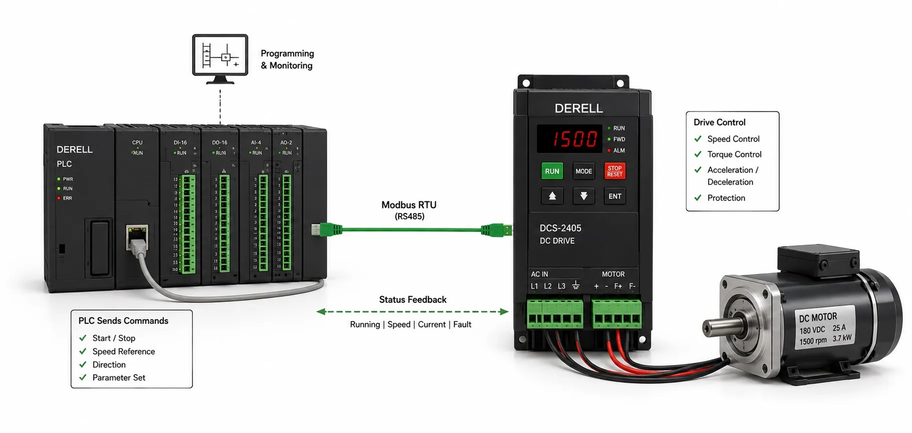
Can a PLC control a DC drive?
Yes. A PLC can start, stop, supervise and send operating references to a compatible DC drive. The connection may use conventional I/O, an industrial network or a combination of both. Even an older drive without a fieldbus option can often be integrated through its existing control terminals.
The important distinction is between machine control and motor control. The PLC coordinates the process; the DC drive controls power delivered to the motor. A PLC output is a command interface, not an armature power supply.
Choose the interface around the information you need
Discrete I/O is suitable for commands and indications such as run, enable, direction, ready and fault. Analogue I/O provides a variable reference or measurement. A network interface can exchange these signals together with additional operating values and diagnostics. The practical choice depends on the number of signals, required update rate, available hardware and maintenance needs.
For a straightforward conveyor, a run command, an analogue speed reference and ready/fault feedback may be adequate. A coordinated production line may benefit from cyclic exchange of speed, current, status and fault data. More communication capability is useful only when the application actually uses it.
Hardwired control still requires an electrical compatibility check
Before connecting PLC outputs to drive inputs, identify the output technology, input voltage and common-terminal arrangement. Relay outputs and transistor outputs are not interchangeable. With transistor I/O, check the sinking and sourcing requirements on both sides. Two devices marked “24 V” are not necessarily ready for direct connection.
The distinction between analogue and digital inputs also matters. A drive's analogue input may accept 0–10 V, ±10 V or 4–20 mA, depending on the model and configuration. Confirm the signal type, reference common, isolation requirements and scaling rather than copying a wiring arrangement from another drive.
Example: if a 4–20 mA channel is configured to represent 0–1500 rpm, 12 mA requests 750 rpm. That establishes the speed demand, not the measured shaft speed. Actual motion must be checked using the drive's feedback or an appropriate encoder. A 4–20 mA interface only provides broken-wire detection when the receiving device supports and is configured for that function.
A matching connector does not establish network compatibility
Depending on the drive and its installed options, integration may use Modbus RTU, Modbus TCP, PROFIBUS, PROFINET or EtherNet/IP. Do not assume that every DC drive supports all of these protocols.
RS-485 describes an electrical interface; it does not automatically mean Modbus. An Ethernet port likewise does not guarantee support for a particular industrial Ethernet protocol. Check the option card, firmware compatibility and PLC-side device description before designing the connection.
For serial networks, verify the device address, baud rate, parity and stop-bit settings. For other networks, configure the relevant addressing and cyclic data arrangement. Cable routing, termination and shielding must follow the requirements of the actual interface.
Define a command-and-status contract
Networked drive control commonly uses a control word, one or more references and a returning status word. The PLC requests actions; the drive reports its operating state. Additional data may include actual speed, armature current, field current and diagnostic codes.
A successful register write does not prove that the drive is enabled or running. It may still be in local mode, waiting for a permissive or expecting another step in its command sequence. Control-bit definitions, register addresses, signed-number formats and scaling must come from the manual for the installed drive and communication profile.
Keep three observations separate: run requested, drive running and shaft at target speed. This makes both commissioning and fault diagnosis more effective. If a run request is present but the drive remains unready, increasing the speed reference will not solve the underlying problem.
Keep fast motor regulation in the appropriate controller
In a typical arrangement, the drive handles the fast current loop and, when configured accordingly, the speed loop. The PLC manages recipes, operating sequences and coordination with the rest of the machine. A PID loop in the PLC might adjust the drive's speed demand to regulate web tension or another process variable.
This division of work should be deliberate. The available motor-control modes and feedback options determine what the drive can regulate locally. A process loop in the PLC does not automatically replace those functions.
No communication link has zero delay. PLC task timing, network update intervals and drive processing all contribute to response time. Applications requiring tight multi-axis synchronization need a suitable motion-control architecture; a working serial connection alone does not establish adequate dynamic performance.
Design the behavior when commands stop arriving
The most revealing integration test is often a lost-command test. Depending on configuration, a drive may retain its previous reference, ramp to a stop or respond in another way. Define the required behavior before commissioning, using the machine's mechanical characteristics and risk assessment.
Consider a disconnected network cable, a lost analogue reference and a PLC entering STOP as separate events. An interface can remain online even when the application is no longer producing fresh commands. Where required, an application-level heartbeat or changing counter can help detect stale data, not just a broken connection.
Recovery needs equal attention. Re-establishing communication should not allow an old run request to cause unintended movement. Define how the drive is acknowledged, how references are restored and when a fresh start request is required. A timeout setting is an operational safeguard, not automatically a safety-rated function.
Separate normal stopping from machine safety
A stop command in an ordinary PLC program is not, by itself, a safety function. Emergency stopping and protective interlocking require an appropriately designed and validated safety-related control system. A safety relay or safety PLC may form part of that system, but the complete path from the input device to the final switching element must meet the application requirements.
The drive's motor-protection functions do not cover every machine hazard. Do not assume that an older DC drive includes STO or another certified safety function. A zero-speed reference does not establish electrical isolation, and removing torque may not safely hold an overhauling load.
Commission the complete sequence, including faults
For a conveyor, a typical operating sequence is to verify process permissives and drive readiness, issue the operating command, apply the speed reference and monitor the resulting motion. The drive controls the DC motor; the PLC checks whether the measured speed and current are consistent with the requested operation.
Verify reference scaling, permitted direction, local/remote selection, normal stopping, fault indication and recovery under controlled commissioning conditions. Record the fault code before resetting. Repeated automatic resets can hide a persistent motor, load or drive problem.
Monitoring current together with speed is particularly useful: increasing current accompanied by falling speed can indicate a developing overload or jam. This process monitoring complements the drive's electrical protection; it should not be used as a substitute for it.