
How scalable are DC drives?
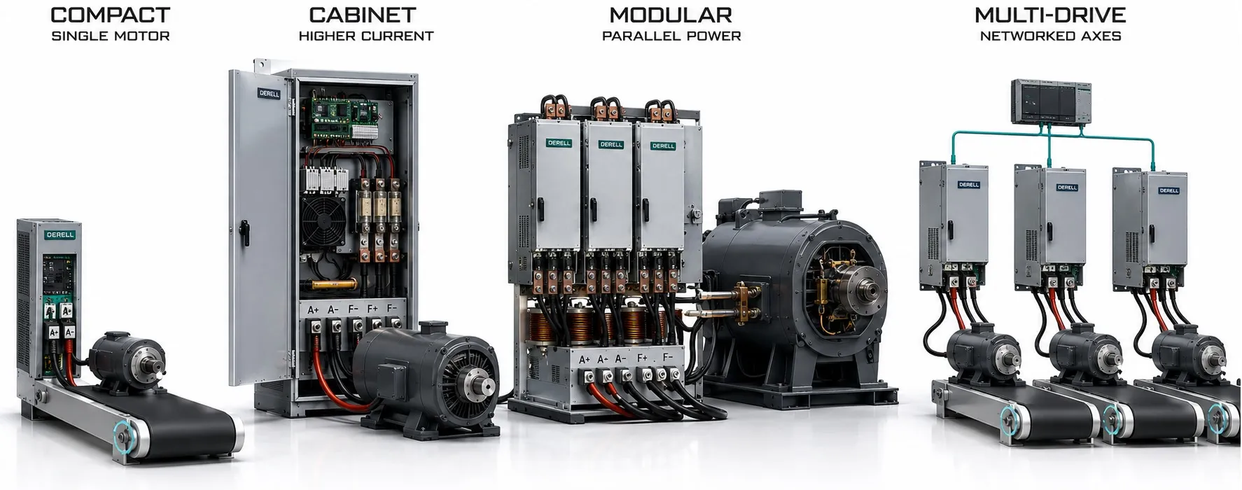
How scalable are DC drive systems?
A production line can grow in several ways: a heavier load on an existing shaft, an additional driven section, more instrumentation or closer coordination with the plant controller. DC drive scalability is the ability to accommodate those changes within defined electrical, mechanical and control limits. The right expansion path depends on what is actually changing.
A communication card may give a DC drive access to a new control network. It does not increase the current its power stage can deliver. Likewise, a product family covering a broad rating range provides a choice of sizes; it does not make every installed unit upgradeable to the largest rating.
Start by defining the expansion
More shaft output calls for a review of the motor, converter and supply. More independently controlled motors usually calls for additional drives. More process information may require extra I/O, feedback interfaces or network capacity. Separating these requirements early makes drive selection more precise and avoids paying for capacity that does not address the actual bottleneck.
The most useful question is therefore specific: Can this installation support the planned load and duty cycle, with the required control performance? A general claim that a drive is “modular” cannot answer that on its own.
Increasing power means checking current, voltage and duty
For a larger motor, establish the required armature voltage, continuous armature current and overload profile. Published power ratings must be read alongside their voltage and operating conditions. Motors with the same shaft power can require different currents if their rated voltages differ.
Example: An existing motor draws 80 A at its rated operating point, and the drive has an applicable continuous rating of 100 A. A replacement motor requiring 125 A continuously at the same armature voltage exceeds that capacity. A short-duration 150 A overload allowance does not turn the converter into a continuous 125 A unit. Overload duration, recovery time and the actual operating environment all matter.
A larger converter may also require changes to cables, semiconductor fuses, contactors, ventilation and any supply transformer or line reactor. These supporting components form part of the capacity assessment. Adding an I/O board or changing a current parameter cannot increase the physical rating of the power stage.
The motor and field supply can set the limit
For a separately excited DC motor, field voltage and current need their own compatibility check. A replacement motor may fit the armature converter rating while exceeding the installed field supply. Any change to excitation hardware must follow the drive manufacturer's supported arrangements.
Keeping the existing motor also requires an honest assessment of its thermal and mechanical capacity. Brush and commutator condition, ventilation and permitted speed remain relevant after a converter upgrade. A higher current setting does not create a higher continuous motor rating. Correct motor-to-drive matching establishes what the installation can actually deliver.
Expanding I/O and connectivity
Where supported, option modules can add analog channels, digital I/O, encoder interfaces or fieldbus connectivity. This can accommodate additional process sensors, operating permissives and reference signals. Check the module type, signal characteristics, available slots and firmware compatibility before treating an expansion as straightforward.
Integration with a PLC also depends on more than a matching protocol name. The controller and drive must agree on command and status data, reference scaling, update timing and communication-loss behaviour. A network connection that is adequate for monitoring may be unsuitable for tightly coordinated process control.
For example, adding a winder may require torque feedback, line-speed information, drive-ready status and web-break detection in addition to a speed command. The interface must support the complete operating sequence, not merely establish communication.
Programmability extends functions, not hardware ratings
Some DC drives provide function blocks, application macros or programmable logic. These features can handle tasks such as reference selection, ramp coordination and process-specific calculations. Their scope varies: a programmable drive is not automatically a replacement for the machine PLC. Execution capacity, supported functions and licensing must be checked for the particular platform.
Firmware updates may introduce supported features or correct faults. They cannot remove the thermal and electrical limits of the installed converter. If an expansion needs a different control strategy, confirm that the necessary power hardware and feedback are available as well as the software function.
Adding driven sections can be more useful than enlarging one drive
A second pull roll or an additional conveyor section changes the architecture of the machine. Where motors need independent speed or torque regulation, each will generally require a suitably rated drive. This approach is common in sectional industrial drive applications.
Sending identical speed references to several drives does not guarantee equal load sharing or accurate position synchronisation. Roll diameters, gearbox ratios, slip and mechanical loading can all differ. Depending on the process, the system may need speed-ratio control, torque sharing or tension regulation with appropriate feedback devices.
Additional sections also change acceleration and stopping behaviour. Assess the dynamic response of the complete line, especially where a speed mismatch could stretch, slacken or break the material being processed.
Shared control does not imply a shared DC power circuit
A common communication network, a common DC supply and parallel converter outputs are three separate arrangements. Conventional line-fed thyristor DC drives should not be assumed to have the same connection options as an AC multidrive system with a shared intermediate circuit. The available arrangements depend on the converter topology.
Chopper-based systems designed for a common DC supply can support that architecture, but voltage compatibility, energy flow, isolation and fault protection need a system-level design. Do not connect the motor outputs of two ordinary DC drives together to obtain more current. Parallel power operation requires an explicitly supported converter arrangement with the necessary current-sharing control and protection.
A wider speed range is not extra torque capacity
On suitable separately excited motors, field weakening can extend operation above base speed. Available torque then falls as flux is reduced at a given armature current. Increasing line speed must therefore be checked against the load's power requirement, the motor's permitted speed and its commutation limits.
Adding a frequently braking or overhauling section also changes the energy balance. Regeneration can recover useful energy where the converter and supply arrangement allow it, but the benefit depends on the operating cycle. An efficiency assessment should use actual braking energy and running time rather than assume that a regenerative drive always provides a large saving.
Retrofitting an existing installation
If the motor remains suitable, replacing its converter and controls may extend the usefulness of the machine. Check the existing tachogenerator or encoder interface, excitation arrangement, signal levels and stopping sequence. Identical parameter numbers or numerical values do not guarantee equivalent behaviour on a different drive.
The business case also depends on maintenance requirements, access to spares and service support. Repeated drive-related faults may originate in the motor, wiring or mechanical load. A new converter will not automatically correct those underlying problems.
Plan for a defined next step
Useful expansion allowances are specific: space for another converter, capacity for an identified future load, spare I/O for planned sensors or an interface for a known control-system upgrade. Buying an oversized drive without a defined future duty is a poor substitute for an expansion plan.
Compare the complete cost: equipment, engineering, production downtime, software tools, commissioning, backups and maintenance training. This gives a realistic view of the strengths and limitations of retaining a DC drive system as production requirements evolve.