
How is the dynamic response in DC drives?
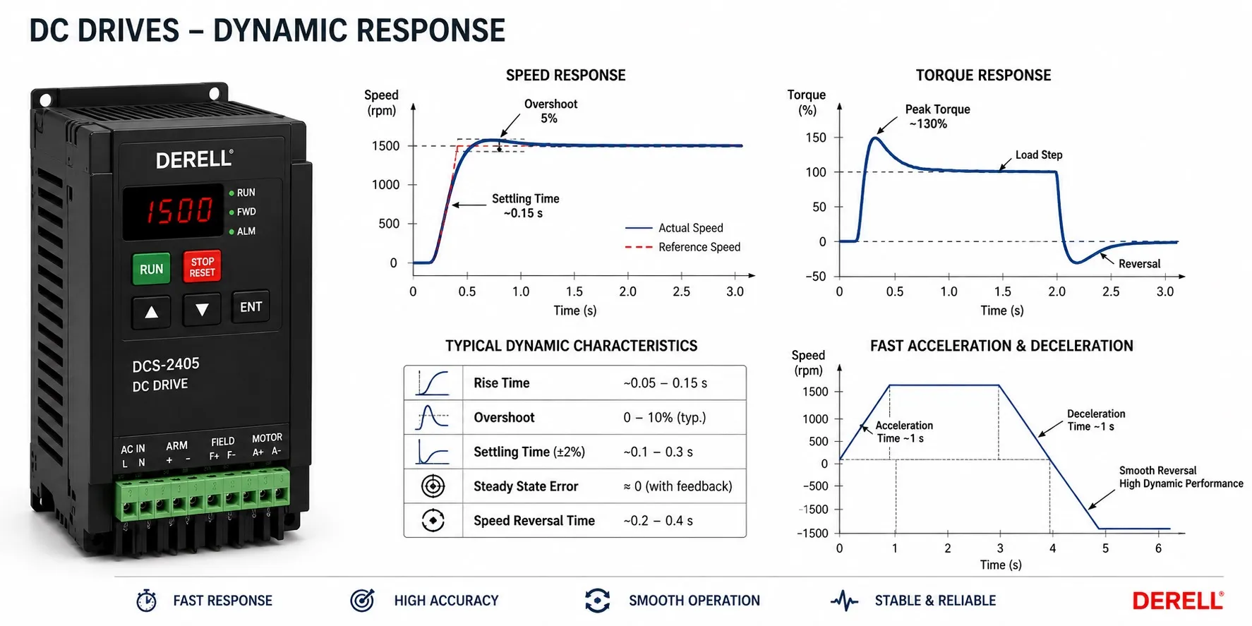
How do DC drives respond to speed and load changes?
A drive’s dynamic response describes what happens between one operating condition and the next. It includes how the motor follows a changing command, how much it overshoots, and how well it recovers when the load suddenly changes. Fast acceleration is only one part of the picture.
A well-engineered DC drive system can deliver responsive torque and accurate speed regulation. That does not establish a universal advantage over AC equipment. Modern vector-controlled VFDs and matched servo systems can also provide demanding dynamic performance.
Start with two different questions
How well does the motor follow a command? When the speed reference changes, the system must accelerate or decelerate toward the new target. The result can include delay, overshoot and oscillation before a stable speed is reached.
How well does it reject a load disturbance? A conveyor running at constant speed may encounter additional material. The speed initially drops, the controller requests more torque, and the motor recovers. The depth of that speed dip and the recovery time describe a different aspect of performance from command following.
A machine can have accurate steady-state speed yet respond poorly during a sudden load change. Similarly, a short acceleration time does not prove good positioning performance.
Use defined response measurements
Rise time measures how long the response takes to pass through a specified portion of a commanded change. Overshoot measures how far the response exceeds its target. Settling time measures how long it takes to enter and remain inside a stated tolerance band.
Those definitions must accompany any numerical comparison. A settling time measured with a wide tolerance band cannot be directly compared with one measured using a much tighter band. The load, command size and operating speed also need to be stated.
A motor that reaches its target quickly but then oscillates may delay the next production operation. For an indexing axis, the useful result is often the time until the mechanism is stable enough to perform its task, rather than the first instant it crosses the target.
Electrical torque response is not mechanical acceleration
At approximately constant field flux, DC motor torque is approximately proportional to armature current. This makes current regulation a direct way to influence torque production. A speed controller can request additional current when a load disturbance slows the motor.
However, current cannot change instantaneously. Winding inductance, available voltage, back EMF and converter limits influence how quickly it can rise or fall. A quoted current-loop response describes this electrical behavior, not the time required for a complete machine to change speed.
The mechanical relationship can be simplified to α = (Tmotor − Tload) / Jeq. Angular acceleration depends on net torque and the total inertia referred to the motor shaft. Here, opposing load torque includes the relevant mechanical losses.
If inertia doubles while net accelerating torque remains unchanged, acceleration is approximately halved. The same limitation applies when selecting a servo motor. Faster electronics cannot remove the inertia of the driven mechanism.
The control loops must work together
A typical cascaded arrangement has an inner current loop and an outer speed loop. A positioning application may add a position loop outside them. The inner current loop is generally designed to respond faster, allowing it to carry out the torque demand produced by the speed controller.
Increasing controller gain can improve response up to a point. Excessive loop gain may instead increase overshoot, amplify measurement noise or excite mechanical resonance. Integral action helps remove persistent error, but saturation behavior matters when the controller reaches a current limit.
Automatic tuning can provide a useful starting point. It does not eliminate the need for correct motor data, suitable mechanical connections and evaluation under the intended load. A growing winding roll or changing payload may alter the dynamics substantially.
Feedback quality and filtering affect the result
An encoder, tachogenerator or electrical speed estimate supplies the information used by the controller. A tachogenerator measures speed-related information; it does not directly provide position. Encoder resolution and the method used to calculate speed become particularly important at low rotational speeds.
Filtering can reduce noise but also introduce delay. A heavily smoothed display may look excellent while hiding short speed excursions. A clean-looking signal should therefore not be confused with a fast, accurate control response.
The appropriate feedback arrangement includes the sensor interface, mechanical coupling, cable installation and grounding. Poor feedback installation cannot reliably be corrected by controller tuning alone.
Converter topology places additional limits
A line-commutated thyristor converter adjusts output in relation to available conduction opportunities in the supply waveform. A transistor-based PWM converter operates with a different switching process. These differences influence current ripple and the achievable electrical control response.
Nevertheless, switching frequency or controller sampling rate alone does not determine machine settling time. Motor characteristics, delays, current limits and mechanical resonance remain part of the system. The same caution applies to the carrier frequency of an AC variable frequency drive: it is not the same quantity as speed-control bandwidth.
Ramps define the request; available torque determines what is possible
An acceleration ramp determines how quickly the reference changes. The feedback controller determines how the motor follows that reference. Shortening the ramp does not create additional torque. If the required current exceeds the permitted limit, actual speed may fall behind the commanded trajectory.
Smoother motion profiles can reduce mechanical shock and resonance excitation, sometimes at the expense of a longer move. The appropriate compromise depends on the process: a winding machine, cutting axis and centrifuge do not necessarily need the same response shape.
During deceleration, the system must also handle stored mechanical energy. A suitable regenerative converter can return energy to the supply; a correctly designed braking-resistor arrangement dissipates it as heat. Regeneration alone does not guarantee a shorter stop. Braking torque, energy-handling capacity and mechanical limits still apply.
Rapid reversing also requires the appropriate converter operating capabilities. A one-direction drive cannot become a four-quadrant converter through parameter changes alone.
Make a fair comparison with VFD and servo systems
A basic V/f-controlled AC drive may behave differently from a closed-loop DC installation. That comparison does not represent every AC drive. Advanced vector-control and direct-torque-control systems can deliver fast, precise motor control.
Servo performance also needs to be examined beyond the product label. Motor inertia, peak and continuous torque, feedback quality, following error and settling time all matter. Servo describes a control approach, and a DC motor can form part of a servo system.
For a positioning axis, position-loop tuning must suit the transmission. Backlash, flexible couplings and belt compliance can limit achievable performance even with a responsive drive.
What should be recorded on the actual machine?
Following the manufacturer’s commissioning procedure, evaluate speed reference, actual speed, armature current, current-limit status and position error where applicable. Examine command tracking and load-disturbance recovery separately. A satisfactory unloaded result does not establish performance at production load.
When collecting data through PLC integration, check the recording interval. A slowly refreshed HMI can miss brief overshoot or current peaks. A drive’s suitably configured trace tool may reveal behavior that is invisible on the operator display.