
How is debugging performed in PLCs?
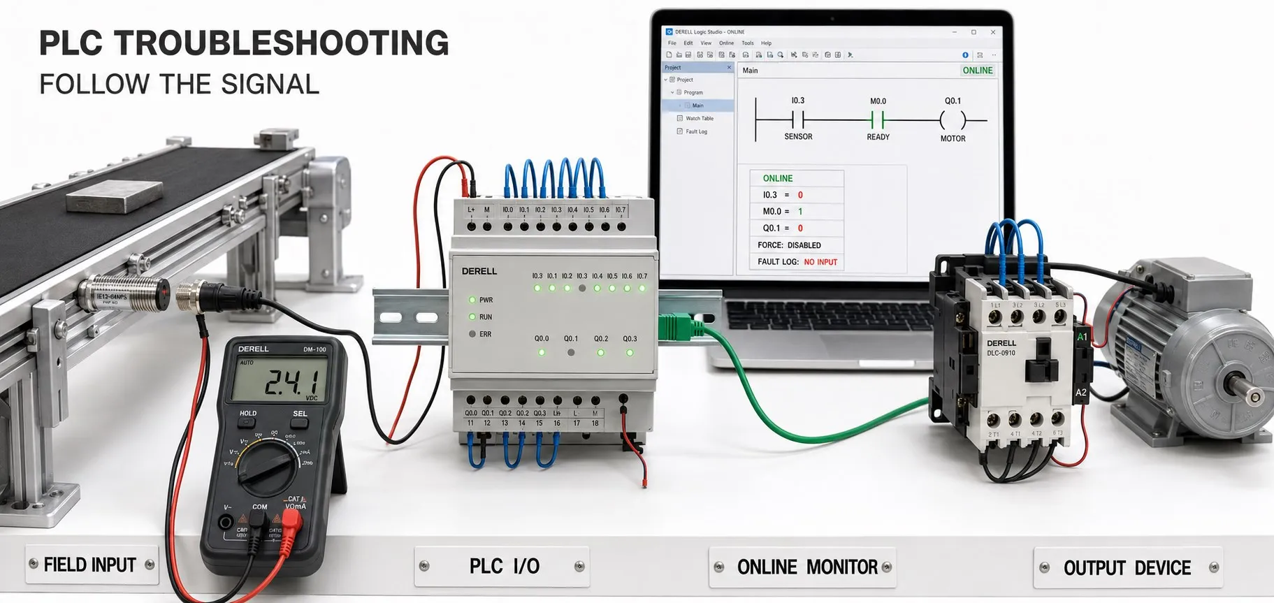
Hello everyone,
PLC debugging means finding why actual behaviour differs from the intended operation. A motor that will not run, an incorrect count or a misleading temperature reading does not always indicate a software defect. Field wiring, I/O mapping, program logic, communication and mechanical conditions all need consideration. Alongside PLC programming, effective troubleshooting requires evidence of where a signal or decision changes.
1. Define the symptom and verify the controller and project
Replace “the machine does not work” with the specific action that is missing: is the start request absent, is a run permissive missing, or does the equipment fail to move despite an active output? Record the operating mode, time of the fault, recent changes and alarm codes. Check the CPU's RUN/STOP state, module diagnostics and, where available, the event log. Clearing alarms or cycling power before recording the cause can remove useful evidence.
The PLC programming software must support the CPU and firmware version. Verify the identity of the online controller and confirm that the local project matches the running application. Preserve the existing project, parameters and hardware configuration before making changes. Uploading from a PLC does not always recover the complete original source project. On a CODESYS-based system, for example, source code may need to have been downloaded separately to the controller.
2. Follow the signal from the field
An illuminated LED on a sensor does not prove that the relevant PLC variable is correct. Compare the sensor state, input module channel, program variable and process permissive separately. An incorrect address, wrong I/O mapping, input filtering or incompatible signal type can produce similar symptoms.
On the output side, distinguish the program command, physical output channel and equipment feedback. A motor-run bit can be true while module power, an interposing relay, a drive permissive or the motor circuit prevents movement. A logic value on screen is not proof of physical operation. Wiring interventions require the machine to be placed in a safe condition and the relevant energy sources isolated.
3. Monitor related conditions together
A watch table should contain more than the final output. Include the start request, automatic/manual mode, process permissives, sequence step, timer status, fault bit and feedback. This turns “why is the output off?” into a search for the missing condition. Where one function block is used for several devices, monitor the correct block instance.
Follow the condition path in Ladder Diagram or FBD. In Structured Text, inspect comparisons, assignments and data types. With SFC, check the active step and transition condition. A cross-reference search identifies other blocks or tasks writing to the same variable. A value that looks correct at one observation point may change elsewhere in the cycle.
4. Use trace recording for intermittent and timing faults
The watch display refresh rate differs from the PLC execution cycle, so a brief signal may never appear on screen. Where supported, a trace recording captures variable values with time information to reveal the order of events. Compare start, permissive-loss and fault signals in the same recording. Select the sampling interval and trigger for the event being investigated, and account for the recording's possible effect on task execution time.
For incorrect counts, check input filtering, pulse duration and edge detection. If ordinary input acquisition and program scanning cannot capture the pulses, a suitable high-speed counter may be needed. A timer repeatedly reset by the program, or a block called only on some cycles, can also behave unexpectedly. Task cycle time and watchdog records help identify execution-time problems.
5. Separate analog acquisition from scaling
Check the raw input value, the engineering-unit value and the displayed value separately. Confirm the channel's current/voltage setting, sensor range, data type and unit. For a linear sensor with a 4–20 mA output representing 0–10 bar, 12 mA corresponds to 5 bar. The PLC module's raw numeric range depends on its model and channel configuration.
Even a correct sensor reading can be misrepresented by incorrect scaling, overflow or loss of precision in integer calculations. For PID control problems, monitor the process value, setpoint and control output together. Changing PID gains to compensate for a measurement error does not fix its cause. For broken-wire or out-of-range conditions, inspect module diagnostics and the configured response.
6. Check communication and display faults
For data from remote I/O or a drive, check validity and freshness as well as the value. Retaining the last value after a lost connection can leave the display showing an old condition. With PROFINET, inspect device and module diagnostics. With Modbus RTU, check device addressing, serial settings, register mapping and timeout records.
Does the HMI read the correct PLC tag? Are its data type, unit and scaling correct? In SCADA, check the last-update time and data quality where available. A problem in PLC-to-SCADA data exchange does not necessarily mean the PLC logic is wrong. Diagnose a control fault separately from a display fault.
7. Understand the limits of simulation
Simulation can test sequences, calculations, boundary values and missing-input conditions without operating the physical machine. Support and scope depend on the software and target controller. As with CODESYS debugging tools, simulated I/O, communication and execution timing can differ from the real controller.
Passing a simulation does not establish that the application will work correctly in the plant. Sensor response, electrical connections, drive behaviour and mechanical delays still need validation. Test cases should cover missing sensor feedback, timeouts, communication loss and restart conditions alongside normal operation.
8. Writing a value and forcing it are different operations
Writing or modifying a value changes a variable according to the platform's supported method; program execution or an I/O update may overwrite it again. Forcing applies an override to supported variables or I/O. Supported addresses and the points at which force values are applied vary between manufacturers. Force is not a universal mechanism that fixes every variable identically on every PLC.
Use forcing only with the machine in a safe, controlled test condition, never to conceal a production fault or bypass a safety condition. On some systems, closing the software or disconnecting does not end the force job. Remove forces using the manufacturer's procedure and confirm on the controller that no active forces remain. Begin diagnosis with observation wherever practical.
9. Breakpoints and single stepping are platform-dependent
A breakpoint stops program execution at a selected location where supported. Single stepping lets you inspect execution one step at a time. Availability depends on the CPU, runtime, firmware and engineering software. A feature present in a simulator is not necessarily available on the physical controller.
Stopping program execution does not necessarily stop the physical process. Other tasks may continue, I/O updates can be affected and output behaviour depends on the target system. Use these tools in a test environment where their effects have been assessed. For an operating production line, monitoring, event logs and suitable trace recording are often more practical.
10. Example: The start button is pressed, but the motor does not run
If the start request never reaches the PLC, inspect the input channel, address and signal path. If the request arrives but no motor command is generated, check the operating mode, process permissives, active faults and sequence step. If a command exists but there is no movement, investigate the physical output path and equipment status.
For a motor controlled by a variable frequency drive, review drive-ready status, command source, speed demand and fault code together. In a servo system, also inspect enable status, homing requirements and the motion block's status/error information. Forcing an output to make the motor turn does not resolve the fault under normal operating conditions.
Verify the correction and record the change
Once the root cause is identified, make a controlled correction rather than changing several unrelated settings at once. Reproduce the original fault condition and check that associated operations still work correctly. Remove temporary test values, forces and debugging settings, then verify the normal operating configuration.
The change record should include the symptom, cause, correction, test result and project version. Update the project backup and electrical drawings. Keep program-editing permissions and remote access controlled as part of PLC system security. This makes it possible to establish what changed, why it changed and which version contains it.