
AS/NZS 3008.1.1
Cable size depends on more than the load current
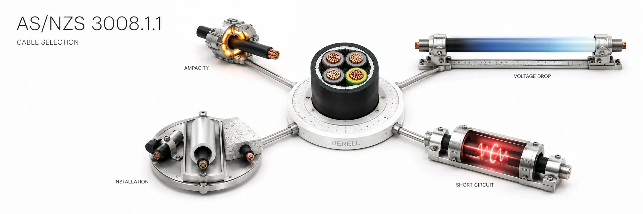
AS/NZS 3008.1.1 provides a cable-selection method based on current-carrying capacity, voltage drop and short-circuit temperature rise. It belongs to the joint AS/NZS standards family, with this part addressing typical Australian installation conditions. At the catalogue check on 15 October 2026, the current edition was 2025, replacing the 2017 edition.
The 2025 scope covers common installation methods at working voltages up to 0.6/1 kV at 50 Hz AC and up to 1500 V DC. This does not make every cable within that voltage range suitable for every environment. Cable cross-section selection must also consider product characteristics and the AS/NZS 3000 installation requirements.
Editor's note: The NZ in AS/NZS does not make the tables in 3008.1.1 identical to those for New Zealand conditions. Part 3008.1.2 separately addresses typical New Zealand conditions. The current catalogue edition and the edition referenced by local legislation may also change on different dates.
Identify the cable and its actual installation conditions first
Correctly identify the copper or aluminium conductor, insulation, core arrangement and number of loaded conductors. A given cross-section does not have the same current rating in free air, conduit, thermal insulation and soil. Outdoor and underground cable selection must also account for mechanical strength, moisture and the product's intended application.
Finding the correct row in a current-capacity table by conductor size is only the start: the installation-method column and table notes must also match. Ambient temperature, grouping, burial depth and soil thermal properties affect the result. There is no single universal ampere rating for a conductor cross-section.
How correction factors change usable capacity
Suppose a hypothetical cable has a reference rating of 100 A, with an applicable temperature factor of 0.90 and grouping factor of 0.80. Where the relevant method permits these factors to be multiplied together, its corrected capacity is 100 × 0.90 × 0.80 = 72 A. It is therefore inadequate for an 80 A continuous load. These figures are illustrative and are not taken from a particular conductor-size table in the standard.
The answer is to reassess the cross-section, route or grouping arrangement, rather than continue using the 100 A reference value. Cooling conditions matter when assessing cable heating. A cable wound on a reel also has different thermal conditions from one laid out in the open. Do not apply the same correction twice if an effect is already included in the selected table.
Coordinate protection with the corrected cable rating
A basic check for general overload protection is Ib ≤ In ≤ Iz. Ib is the design load current, In the protective device's rated or relevant setting current, and Iz the cable capacity under its actual installation conditions. The fuse current rating cannot be selected solely from the cable's uncorrected reference rating.
Protective-device selection also considers operating characteristics and conditions. Requirements such as I2 ≤ 1.45 × Iz are particularly relevant when assessing fuse operation; I2 is the current that operates the protection within the specified time. Increasing the fuse rating does not make an undersized cable acceptable. These relationships are checks within a complete coordination assessment, not a standalone selection recipe.
Keep units and circuit type consistent in voltage-drop calculations
Where the appropriate circuit coefficient is given in mV/A/m, voltage drop is calculated as ΔV = coefficient × current × route length / 1000. Assuming a suitable three-phase coefficient of 1.5 mV/A/m, a 40 A load over 50 m gives ΔV = 3 V. On a 400 V circuit, that is 0.75%. The example does not recommend a conductor size.
If the coefficient already includes the single-phase or three-phase circuit relationship, do not multiply again by 2 or √3. Calculations using R and X separately must account for the circuit formula, power factor and conductor temperature. For a long cable run, consider feeder and final-circuit drops together. Assess motor-starting voltage drop separately from steady operation; the percentage in this example is not a universal installation acceptance limit.
Short-circuit withstand is different from a breaker's kA rating
During a short circuit, the cable must withstand the thermal stress until protection clears the fault. Where the adiabatic method is applicable, use I²t ≤ k²S². S is conductor cross-section, t the clearing time, and k depends on conductor material and initial and permitted final temperatures. k is not the same constant for every cable.
A breaker with adequate breaking capacity does not automatically establish cable withstand. At the same fault current, quadrupling the clearing time quadruples I²t; for the same k, the minimum required cross-section doubles. Also check whether protection operates quickly enough at the lower fault current available at the far end of the circuit.
Include neutral, protective conductors and terminations
Neutral and protective conductors have different functions. Do not reduce the neutral cross-section without assessing load imbalance and harmonic currents. Protective earthing requires separate checks of conductor size and fault operation. Completing the phase-conductor ampacity calculation does not complete the selection of every conductor.
High-temperature insulation does not establish that every connected device or terminal can operate at that temperature. Cable lugs, ferrules and crimped connections must suit the conductor material. Check the product data, termination temperature limits and the manufacturer's connection requirements together.
Additional checks for DC systems and construction sites
The DC coverage of the 2025 edition matters for PV and battery cable selection, but it does not remove cable voltage, environmental or connection requirements. Assess DC fuse selection and breaking capacity separately. On construction sites, cable calculations must also be considered alongside the layout, mechanical protection and inspection requirements of AS/NZS 3012.
Record the edition, table and column, cable construction, installation method, correction factors, load, length, voltage drop and fault-clearing time. This makes the result more than an isolated mm² value: another technical person can review how it was obtained.
Related guides
Cables, sockets and connectors
Converting AWG and mm²
Differences between fuse types
Related AS/NZS standards
Sources
NSAI: AS/NZS 3008.1.1:2025 scope and current edition
MBIE Building CodeHub: AS/NZS 3008.1.2 for New Zealand conditions
Prysmian: cable selection, rating factors and voltage-drop principles, 2015 technical guide
CMI Electrical: cable calculation method and short-circuit thermal withstand
Schneider Electric Electrical Installation Guide: coordinating conductors and protective devices
Schneider Electric Electrical Installation Guide: single-phase and three-phase voltage drop
IEC 60364-5-52: wiring systems, harmonics and electrical connections
Manufacturer guides support the calculation principles; tables based on earlier editions must not be treated as 2025 data. Use the applicable full standard, local rules and product information together for actual design.