
Gas Filled Fuses
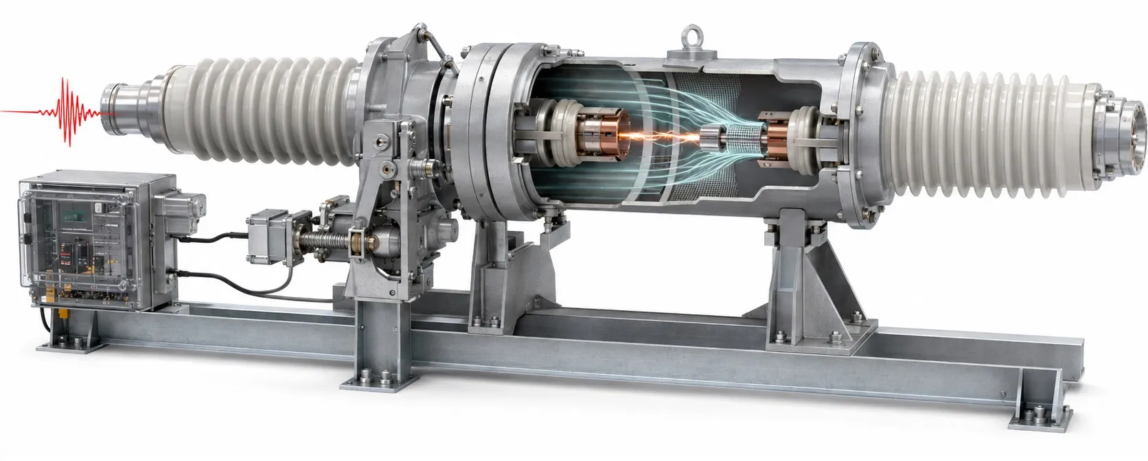
A protective device that diverts voltage surges
Hello everyone,
A gas discharge tube (GDT), sometimes loosely described as a “gas-filled fuse,” helps protect electronic circuits against short-duration overvoltage transients. A GDT and a conventional melting-element fuse perform different jobs. A fuse opens the circuit under an overcurrent condition. A GDT switches from high impedance to low impedance when the voltage across it becomes high enough, creating an alternative path for surge current. This behavior is useful in telecommunications, data interfaces and correctly designed power-input protection circuits.
Construction and operating sequence
The hermetically sealed body is commonly ceramic; glass may also be used, depending on the design. It contains two or three electrodes and a gas mixture at a controlled pressure. Neon and argon are examples of gases used. Electrode spacing, gas composition and gas pressure jointly determine sparkover characteristics. Describing the gas simply as an “arc-extinguishing filling” misses the central mechanism of a GDT.
During normal operation, the GDT has a high insulation resistance and carries only a very small leakage current. When a transient reaches its sparkover conditions, the gas ionizes, a discharge develops and the device enters a low-impedance conducting state. Depending on the circuit, surge current is diverted between two lines or between a line and a protective reference. It does not necessarily flow to earth in every GDT application.
After the surge, the discharge extinguishes when current and voltage fall to conditions that no longer sustain the arc. The device then returns to its high-impedance state. The sparkover voltage immediately before conduction and the arc voltage during conduction are different quantities. Both matter when assessing the voltage stress on sensitive electronics.
How it differs from a fuse, MOV or TVS
A metal oxide varistor and a TVS diode clamp voltage within their intended operating ranges. Once triggered, a GDT carries surge current at a low arc voltage, exhibiting the switching behavior known as crowbar protection. A complete surge protective device may combine GDTs, varistors and other components. An individual GDT should not be treated as a complete protective assembly.
High surge-current capability and low capacitance are useful GDT characteristics. However, voltage can rise before initial sparkover. Sensitive circuits may need an additional clamping stage coordinated with the GDT. Hybrid arrangements also connect a varistor in series with a GDT; topology and component coordination must follow the manufacturer's application guidance.
Which specifications matter?
DC sparkover voltage: This is measured using a slowly rising test voltage. Normal line voltage, tolerances and expected operating variations must not trigger unwanted conduction. The rating does not mean that the protected circuit can never experience a higher instantaneous voltage.
Impulse sparkover voltage: Under a rapidly rising transient, the sparkover voltage is generally higher and depends on the specified rate of voltage rise. Read it together with the datasheet test conditions. A single voltage marking on the component is insufficient to establish protection for a sensitive input.
Impulse discharge current and waveform: For example, 5 kA, 8/20 µs describes a current capability evaluated under the stated impulse test. It is neither a continuous 5 kA rating nor a 5 kA fault-current interrupting rating. Consider the waveform, number of operations and permitted parameter changes together. Selecting a GDT by comparing this figure with a fuse's ampere rating is incorrect.
Follow current and extinction conditions: The supply may continue feeding current through the GDT after the transient has ended. Check follow-current and holdover characteristics, especially in DC circuits and mains applications. An ordinary signal-line GDT should not be connected directly across the mains merely because its sparkover rating appears suitable. Any required DC fuse, current limitation or disconnection arrangement must be designed separately.
Capacitance, insulation and mounting: The device must suit the line bandwidth, operating temperature, electrode arrangement and package requirements. An SMD GDT and an SMD fuse do different jobs. Thermal protection is another separate function: a thermal fuse is selected around a temperature limit. Assess the fuse-selection requirements separately for the complete protection chain.
Practical considerations in industrial systems
An RS-485 line on a long field cable, an Ethernet interface and a supply cable feeding outdoor equipment can have different protection requirements. The same GDT cannot be used indiscriminately at power-supply inputs and low-voltage communication ports. Consider signal levels, common-mode voltage, isolation requirements and surge withstand capability together.
For example, a field device powered from 24 V does not automatically require a “24 V GDT.” Selection depends on the highest real line voltage, sparkover tolerance, the input's transient withstand capability and any secondary protection. Where the design diverts current to earth, earthing and equipotential bonding form part of the protection. Long, indirect connections can increase the voltage remaining at the equipment even when the component itself is suitable.
Inspection, failure and replacement
Repeated surges and excessive stress can change sparkover characteristics or cause permanent failure. Some models include a dedicated mechanism that creates a short circuit when overheated; this feature must not be assumed for every GDT. If an input fuse has opened, investigate the protective components rather than simply replacing the blown fuse.
A healthy GDT will usually appear open-circuit on a standard multimeter. That reading does not verify its sparkover voltage or remaining surge capability. Appropriate test equipment and the manufacturer's acceptance limits are needed. General fuse-replacement indicators cannot be applied directly to a GDT. Follow safe isolation and replacement procedures and the maintenance requirements of the protection circuit.
Related information and product selection
Understanding the differences between fuse types helps explain why a GDT cannot replace an overcurrent fuse. Fuse standards address the fuse side of the design; GDTs require their own applicable product and test requirements. ITU-T K.12, which covers GDT characteristics for telecommunications installations, illustrates this distinction.
Technical references
TDK: GDT applications and data-interface protection
TDK: Construction and characteristics of gas-filled surge arresters
Littelfuse: Gas Discharge Tube Product Catalog & Design Guide
Bourns: First Principles of a Gas Discharge Tube Primary Protector
Bourns: GDTs, MOVs and protection coordination
ITU-T K.12: GDT characteristics for telecommunications installations