
what is plc ladder diagram?
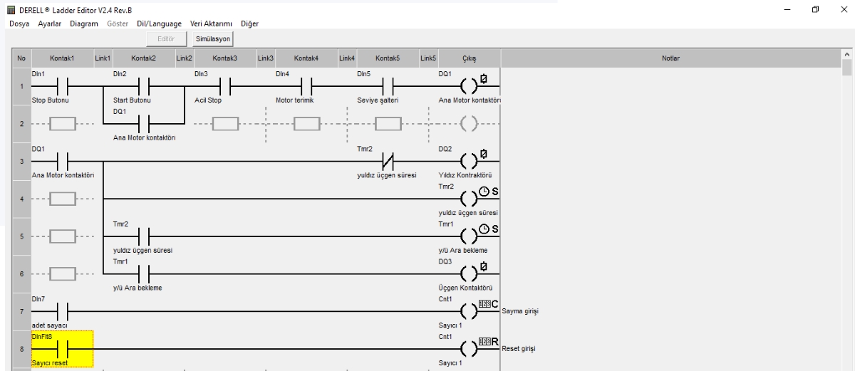
Ladder Diagram (LD) is a graphical language used to program a PLC. Some manufacturers use the names LAD or KOP for the same language. Defined within IEC 61131-3, it uses a relay-control-style layout to organise automation logic visually. Ladder is more than a drawing: it defines conditions and operations that the PLC executes.
How is the ladder structure read? The program consists of networks or rungs. Conditions generally appear on the left, with coils and operations producing results on the right. Vertical rails organise the logic; diagram connections are not physical power cables. Contacts commonly evaluate BOOL variables. Read what each element does in the program without confusing the drawing with electrical wiring.
Normal and negated contacts: A normal contact satisfies its condition when its variable is TRUE; a negated contact satisfies it when the variable is FALSE. A contact tests a variable's state. The on-screen contact symbol alone does not tell you whether a physical button is wired as normally open or normally closed.
Is a physical NC contact the same as a negated software contact? No. For example, a physical NC stop button may be wired so that the PLC input is TRUE during normal operation. Its StopOK variable can then be tested with a normal software contact. Interpret sensor and button signals together with input/output mapping. First determine which physical state makes the input TRUE, then choose the appropriate software contact.
AND, OR and NOT: Conditions in series express AND, alternative parallel paths express OR, and a negated contact applies NOT to its variable. For example, a run permission and a start request may both be required. Check that a parallel branch does not bypass another permission; a holding branch should bypass only the condition it is meant to hold around.
What does a coil do? When the network executes, a normal coil writes the logic result to its BOOL variable: TRUE for a true result and FALSE for a false result. A coil can represent an internal memory variable or an output command. A software coil is not a motor power circuit; physical operation uses suitable output hardware, a contactor or a motor drive. Distinguish a TRUE command from feedback that the device is actually running.
SET and RESET coils: SET writes TRUE when its condition is satisfied; RESET writes FALSE. Unlike a normal coil, a SET does not automatically clear its stored value when the condition later becomes FALSE. Define explicitly how the stored state is released. SET/RESET behaviour and retaining data through a power loss are separate matters; check retention settings independently.
Scan and write order: The PLC CPU executes called programs within configured task scheduling. Writing a variable in an earlier network can affect a later network's result. Writing the same command in several places can make its result depend on execution order. Verify network, program and task order on the target platform; a section that is not called cannot be assumed to update its commands.
What is a seal-in circuit? A seal-in, or holding, arrangement keeps a run request active through its own state after a brief start request ends. In PLC programming, this can be implemented with a holding condition in parallel with the start condition. Stop conditions and run permissions must also interrupt the holding path. Do not design the holding branch to bypass stopping conditions.
A simple run-request example: In this learning example, StopOK is the normal stop permission, OverloadOK is the motor-overload permission, and StartPulse is TRUE for one cycle when a new start request occurs. The network logic can be expressed as RunRequest := StopOK AND OverloadOK AND (StartPulse OR RunRequest);. Assume RunRequest is initially FALSE. This expression explains the logic; it is not a complete motor-control or safety circuit.
Stopping and restarting the example: With permissions TRUE, StartPulse makes RunRequest TRUE; later calls hold it through its own state. When StopOK or OverloadOK becomes FALSE, regular execution of the network makes RunRequest FALSE. Restoring permission alone does not restart it; a new StartPulse is required. Also define pulse generation, initial state and restart behaviour after power returns.
The TON timer: TON is an on-delay function block. For example, with RunRequest connected to IN and five seconds assigned to PT, Q becomes TRUE after IN has remained TRUE for the delay. Calling the block with IN FALSE resets the timing and Q. Call the block regularly, apply its reset condition instead of simply stopping its calls, and use a separate instance for each independent timer.
Counters and edge detection: A standard CTU increments on the rising edge of CU; keeping the signal TRUE does not count a new product on every cycle. Reset clears the count, and the preset defines the completion condition. An encoder or very short pulse may require a suitable high-speed counter. A software counter cannot recover a pulse that input sampling never detected.
Sequences such as star–delta starting: A timer finishing does not by itself prove that a contactor has physically released. Design interlocks preventing simultaneous star and delta operation, suitable transition conditions, and stop/reset behaviour together. An example that only changes timing settings is not a complete motor-starting project.
Is Ladder limited to on/off logic? No. Supported environments also provide comparisons, calculations, data transfers, analog signal processing and PID control blocks. 4–20 mA or 0–10 V data needs appropriate scaling and units. Contact logic and numerical operations can work together in one project. Check available blocks and data types for the selected CPU and software.
How can LD, FBD, ST and SFC work together? Ladder can make conditions and interlocks easy to read; FBD can organise block connections, while Structured Text can handle calculations and data processing. SFC structures sequences with steps and transitions. Choose a method that suits the work. Keep shared-variable access and execution order clear when several languages are used in one project.
HMI and communication: An HMI or SCADA system may send a start request; the PLC evaluates it against operating conditions. Remote I/O and communication updates affect the timing and validity of the information used by the program. Command sent, command accepted and operation complete are different states. Do not assume the last displayed value always represents current field conditions.
What should be monitored while debugging? During debugging, inspect inputs, network results, commands, timer values and counter values together. CODESYS and other programming tools offer different monitoring facilities. Verify stopping, resetting, missing feedback and restarting as well as normal operation. Simulation helps assess logic, but it does not by itself verify actual wiring, hardware delays or physical response.
Ladder and machine safety: Using a graphical program does not establish a validated safety function. The required architecture may use a safety relay or a suitable safety PLC and hardware. Safety programs can also use Ladder; appropriate system design and verification matter more than the language name. Do not treat emergency stopping as equivalent to an ordinary stop contact.