
what is thermocouple?
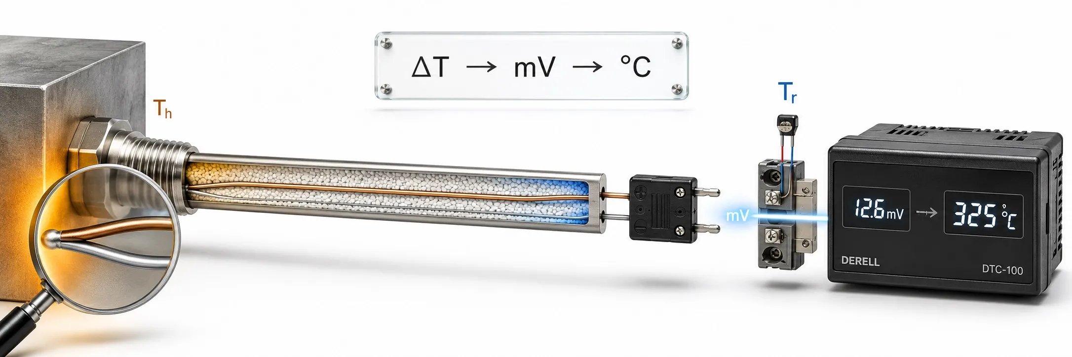
From two different conductors to a reliable temperature reading
A thermocouple measures temperature using the small voltage produced in a circuit made from two conductors with different thermoelectric properties. Industrial documentation often abbreviates it as T/C. The instrument detects this thermoelectric voltage and converts it to temperature using the characteristic of the selected sensor type.
Thermocouples are widely used in furnaces, extruders, plastics machinery, moulds, boilers, dryers and engine testing. Their advantages include a wide temperature range, small probe diameters and adaptable mechanical construction. A reliable result nevertheless depends on the sensor, wiring, instrument settings and installation working together.
Editor's note: A Class 1 sensor does not guarantee that the complete measurement system operates within the same error limit. Wiring, cold junction compensation, measurement electronics and sensor placement also contribute. The sensor's tolerance class alone does not define system accuracy.
How is the thermoelectric voltage produced?
The underlying principle is the Seebeck effect. Two different thermoelements respond differently within a temperature gradient, producing a measurable electromotive force, or EMF, in a suitable circuit. Two homogeneous conductors with identical thermoelectric behaviour do not produce a net thermocouple signal under the same temperature conditions.
The output is usually at the millivolt level; microvolts matter in precision measurement. Describing it simply as “voltage generated at the weld” is incomplete. The EMF relates to the sections of conductor exposed to a temperature gradient. The welded measuring junction defines the physical point whose temperature is to be measured.
The measuring junction, reference connections and CJC
The junction in the process is called the measuring junction or hot junction. The region where the thermocouple alloys transition to the instrument's copper connections forms the reference connections. “Cold junction” is a historical name; that region does not have to be cold. The panel terminals can be warmer than a process being measured below freezing.
Standard tables use a 0 °C reference. An actual instrument measures its terminal temperature and applies cold junction compensation. With suitable conductors and both reference connections at the same temperature, the basic relationship is:
Emeasured = E(Tmeasuring) − E(Treference)
Ecorrected = Emeasured + E(Treference)
The instrument converts the corrected EMF to temperature. Because this characteristic is nonlinear, a single mV/°C factor cannot represent the entire range. IEC 60584-1 specifies reference functions and tolerances; tables, polynomials and ITS-90 explain the conversion basis. An ordinary millivolt input without CJC and the appropriate conversion is not a complete thermocouple input.
What do J, K, T and the other letters mean?
Thermocouple types identify different thermoelement pairs and temperature–EMF characteristics, not simply product names. Type K, using nickel-chromium and nickel-aluminium based conductors, is common in general industry. Type J uses iron and copper-nickel; oxidation of its iron conductor and the process atmosphere are important selection considerations.
Type T uses copper/copper-nickel and is also used at low temperatures. Type E uses nickel-chromium/copper-nickel and can provide relatively high thermoelectric sensitivity. Type N uses nickel-chromium-silicon/nickel-silicon based alloys and is considered for stability in certain high-temperature applications.
Types R, S and B contain platinum and platinum-rhodium based thermoelements and are used at high temperatures. Their suitable atmospheres, protective construction and costs differ from base-metal types. Do not assume that every type provides the same service life in every environment.
Maximum temperature and response time
A type letter alone does not specify the continuous operating temperature of a finished probe. Wire diameter, sheath alloy, insulation, process atmosphere, vibration and exposure time determine the actual limits. The upper temperature in a reference table is not necessarily the permitted operating temperature of the sensor being purchased.
Response time also depends on more than whether the sensor is Type J or K. A thin probe usually responds quickly, but mechanical strength and service life must be considered. Flow velocity, immersion depth, surface contact and the added thermal mass of a thermowell affect the actual measurement response.
Grounded, ungrounded and exposed junctions
A grounded junction is electrically connected to the metal sheath and usually responds faster than an equivalent ungrounded design. An ungrounded junction is insulated from the sheath, providing electrical separation but generally a slower response. An exposed junction directly contacts the medium; it can help in rapid measurements of air and clean gases, but offers limited protection.
“Grounded” does not necessarily mean that the sensor is connected to the installation's protective earth; it describes the junction's relationship to the sheath. The differences between these three junction styles are a separate choice from thermocouple type. An ungrounded design does not eliminate every source of electromagnetic interference.
In mineral-insulated metal-sheathed sensors, conductors are protected within compacted mineral insulation. Known as MI or MIMS construction, this can provide small diameters and mechanical robustness when appropriately designed. IEC 61515 addresses the technical requirements for these thermocouple cables and assemblies.
Can a thermocouple and a Pt100 use the same input?
A thermocouple produces a thermoelectric voltage; a Pt100 is measured through its temperature-dependent resistance and requires a measurement current. Input circuits, wiring effects and error sources differ. A universal instrument may support both, but its wiring and sensor configuration must be changed to the appropriate mode. The Pt100 versus thermocouple comparison helps when assessing which technology suits a process.
Why suitable cable and polarity matter
Extension cable uses the same nominal thermoelement alloys; compensating cable may use different alloys that provide the required thermoelectric equivalence over a specified temperature range. Check type, class, colour identification and operating limits. IEC 60584-3 covers cable tolerances and identification; understanding the difference between extension and compensating cable is part of correct installation.
Changing to ordinary copper cable at an arbitrary point can relocate the reference region. An additional error arises if that transition is at a different temperature from the region represented by the instrument's CJC sensor. Maintain positive and negative polarity throughout the circuit. Reversed wiring does not always produce a simple negative reading; the error also depends on transition temperatures.
Direct PLC connection or a transmitter
A sensor can connect directly to a PLC fitted with a suitable thermocouple input module. The module measures the small voltage, accounts for reference temperature and converts the result for the selected type. Connecting Type K while selecting Type J produces an incorrect result. A standard 0–10 V input is not a direct alternative without the required sensitivity and compensation.
For longer distances or a standard analog input, a temperature transmitter can be used. It performs CJC and conversion at its own thermocouple input, then sends the result as 4–20 mA or 0–10 V. The PLC reads a scaled process signal rather than raw thermocouple EMF. A 4–20 mA output does not prove galvanic isolation; isolation must be checked separately.
A thermocouple does not directly drive a heater or SSR
A thermocouple is a measurement sensor. A temperature controller or PLC compares the temperature with the setpoint and may apply PID control. An appropriate control output drives an SSR or contactor, which switches the heater power. The thermocouple's millivolt output is not intended to drive a power load directly.
The thermocouple needs no external sensor supply to generate its thermoelectric signal. The connected transmitter, PLC module and controller still require electrical power.
Unstable readings in machines with drives
VFDs, servo drives, contactors and motor cables can generate interference affecting the small thermocouple signal. Separate thermocouple wiring from motor output cables and use suitable shielding and input isolation. A temperature jump when a motor starts warrants investigation, but does not by itself prove a sensor fault or ground loop.
Tolerance, calibration and changes over time
Tolerance specifies the permitted deviation from the standard temperature–EMF characteristic. Compliance with a tolerance class does not mean that a sensor has been individually calibrated. Calibration determines its actual deviation from a reference and the associated uncertainty under specified conditions.
At high temperatures, oxidation, contamination and metallurgical changes can cause drift over time. Loss of thermoelectric homogeneity along a conductor can create errors that vary with the temperature gradient. In critical measurements, system measurement uncertainty should include wiring, CJC, the instrument, installation and service effects as well as the sensor.
Where should fault investigation begin?
First verify sensor type, input configuration, polarity and cable type. Then examine loose connections, open circuits, unintended sheath contact and insulation condition. A sensor withdrawn from the process or making poor surface contact can give an incorrect reading even when its electrical circuit is intact.
With a broken sensor, some instruments indicate an upper limit, others a lower limit or a separate fault code; behaviour depends on the instrument and configuration. A continuity check can help identify a break, but does not by itself verify calibration or insulation at high temperatures. Check the sensor, wiring and instrument separately when necessary, using suitable references or a calibrator.
Specify more than a temperature range when ordering
Specify normal and maximum temperature, process medium, probe diameter and length, sheath material, junction style, mounting connection, cable and instrument input type together. Required tolerance and calibration are also part of the order. “A sensor for 0–1000 °C” is insufficient to select the right assembly.
Thermocouple prices depend on more than the J or K designation: sheath alloy, dimensions, precious-metal content, connection construction and calibration affect cost. Correct selection means matching the sensor's physical and electrical properties to the process.
Related topics
Cold junction compensation
Grounded, ungrounded and exposed junctions
Extension and compensating cable
Pt100 versus thermocouple
Sources
Fluke: thermocouple principles, homogeneity and calibration
WIKA: thermoelement types and sheathed construction
Texas Instruments: thermocouple input circuits and CJC (PDF)
NI: wiring, grounding and noise in analog measurement
IEC 60584-1: reference functions and tolerances
IEC 60584-3: extension and compensating cables
IEC 61515: mineral-insulated metal-sheathed thermocouples