
What Is Thermocouple Cold-Junction Compensation?
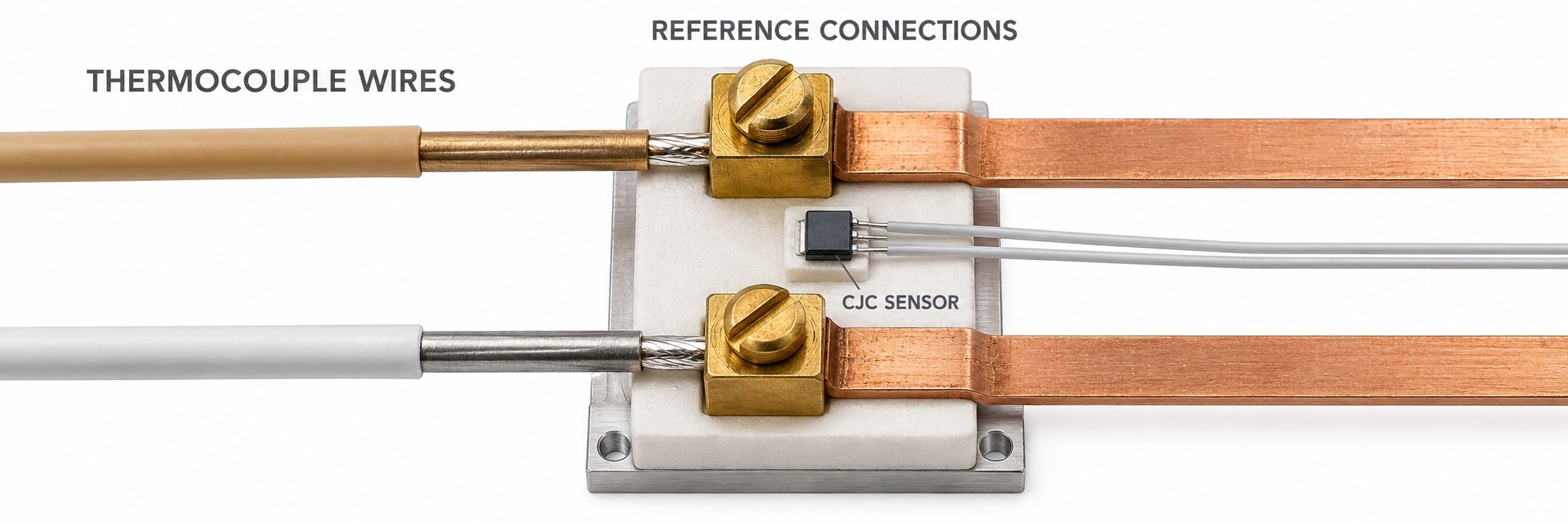
An accurate reading needs more than the sensing tip temperature
Cold junction compensation, or CJC, accounts for the reference connection temperature when determining the measuring junction temperature. A thermocouple's voltage does not depend on the sensing tip alone: the temperature of the reference connections also affects the result.
The Seebeck effect produces thermoelectric voltage when temperature gradients exist along two different conductors. The voltage is not generated solely at the welded bead. In a circuit with suitable, homogeneous conductors, the measured voltage is the difference between the EMF values associated with the measuring and reference temperatures.
Editor's note: A “cold junction” is not a cooling device. The reference terminals can be warmer than the measuring junction: the sensor might measure −50 °C while the panel terminals are at +30 °C. CJC accounts for the actual reference temperature; it does not cool the terminals.
Where are the reference connections?
When the two thermocouple alloys transition to the instrument's copper connections, two separate metal junctions are formed. It is important that they are at the same temperature. With suitable extension wiring continuing to the instrument terminals, the reference region is defined there. The CJC sensor must represent that region; measuring the average air temperature inside the panel is not enough.
Standard temperature–EMF functions use a 0 °C reference. A properly prepared melting ice-water bath can physically establish this reference in a laboratory. Industrial instruments instead use the measured terminal temperature to calculate the equivalent reference condition electronically. The calculation relates to IEC 60584-1 and ITS-90 reference tables.
The instrument uses two kinds of temperature information
A thermocouple input PLC module measures the small voltage arriving from the sensing junction. An RTD, thermistor or semiconductor temperature sensor near the terminals also measures the reference region. This second temperature sensor measures the input connection temperature, not the process. Using an RTD such as a Pt100 for CJC does not turn the process thermocouple into a Pt100.
The instrument converts the reference temperature to an equivalent EMF for the selected thermocouple type, adds it to the measured voltage, then converts the total voltage to temperature. Digital instruments may use tables, polynomials or suitable interpolation; analog compensation circuits also exist.
The calculation: compensate voltage before converting to temperature
Let Tm be the measuring junction temperature and Tr the reference connection temperature. E(T) is the selected type's EMF function with a 0 °C reference. In the ideal case, with suitable conductors and both reference transitions at the same temperature:
Emeasured = E(Tm) − E(Tr)
Ecorrected = Emeasured + E(Tr)
Tm = E−1(Ecorrected)
E−1 means the inverse conversion from voltage to temperature. It does not mean division by E. Because the thermocouple characteristic is nonlinear, directly adding the terminal temperature in degrees to the temperature obtained from the measured voltage is generally incorrect.
Worked example: why simply adding 25 °C is wrong
In Texas Instruments' educational example, a Type K thermocouple input measures 24.904 mV. A table with a 0 °C reference associates this voltage with approximately 600 °C. However, the instrument terminals are at 25 °C, which corresponds to approximately 1.000 mV for Type K.
The instrument calculates 24.904 + 1.000 = 25.904 mV. Converting that total voltage gives approximately 623.5 °C. Simply calculating 600 + 25 = 625 °C introduces about 1.5 °C of error in this example. These are rounded educational values; an actual instrument uses the appropriate reference function.
The CJC sensor must represent the actual terminal temperature
If the CJC sensor measures 30 °C while the metal transitions are at 35 °C, the instrument uses incorrect reference information. A nearby power supply, module self-heating or a fan cooling only one side of the terminals can create a thermal gradient. Precision inputs keep connections isothermal, meaning as close as possible to the same temperature, with good thermal coupling between the CJC sensor and that region.
A multichannel module may share one CJC sensor, provided it represents all relevant terminals with sufficient accuracy. Opening the panel can cause a temporary error if the sensor and connections cool at different rates. A reading that changes when the panel opens does not by itself prove a CJC fault.
Intermediate metals and an incorrect copper transition
The law of intermediate metals states that inserting another metal into a conductor introduces no additional net EMF in the ideal case when the two new junctions are at the same temperature. This does not make ordinary copper cable suitable everywhere. The transitions from the two thermocouple alloys to copper form a reference region whose temperatures must also be accounted for.
Use appropriate extension or compensating cable up to the instrument terminals. If thermocouple wiring transitions to copper in a remote junction box, the instrument's CJC sensor does not measure that box's temperature. An additional error arises when the remote transition and instrument reference region have different temperatures. The difference between extension and compensating cables, alloy selection, polarity and specified cable temperature limits matter here.
Application in PLCs, controllers and transmitters
A temperature controller or PLC module with a genuine thermocouple input applies compensation and linearization for the selected type. If a Type K sensor is connected but Type J is selected, both the reference voltage calculation and temperature conversion use the wrong characteristic. That is an incorrect input configuration, not a failed CJC sensor.
A temperature transmitter near the thermocouple can perform CJC at its own input and convert the temperature to a 4–20 mA or 0–10 V signal. Wiring after this conversion is no longer a thermocouple circuit; the PLC scales the standard analog signal. This can help over long distances, but transmitter accuracy, isolation and environmental limits must also be considered.
Which errors does CJC leave unresolved?
CJC does not correct sensor tolerance, reversed polarity, damaged alloys or electrical interference from a VFD. A grounded, ungrounded or exposed junction still requires CJC. Assess measurement uncertainty using contributions from the sensor, wiring, terminal temperature distribution, CJC sensor and measurement electronics together.
Calibrator checks: two active CJC functions can be correct
In thermocouple simulation mode, a suitable calibrator accounts for its own terminal temperature when producing the output voltage. Connected with the correct thermocouple or extension wire, the receiving instrument also compensates at its own terminals. Both CJC functions being active can be a normal part of this arrangement; it does not automatically mean compensation has been applied twice incorrectly.
A direct millivolt test is different. When a 0 °C reference table voltage is applied through copper test leads to check voltage-to-temperature conversion alone, the instrument's CJC is disabled or its reference set to 0 °C as specified by the test procedure. Leaving normal internal CJC enabled adds the terminal correction to the result. Therefore, millivolt testing, thermocouple simulation and verification of the complete measurement chain are different tests.
When an external ice point or another reference system is used, configure the instrument for that arrangement. Check sensor type, wiring and polarity first, then reference mode and terminal thermal conditions. Test several temperature points with the calibrator and observe the manufacturer's warm-up and stabilization requirements. Disabling CJC is not a troubleshooting remedy for normal industrial measurement.
Related topics
The Seebeck effect
Reference tables, polynomials and ITS-90
Extension versus compensating cable
Thermocouple system measurement uncertainty
Sources
Analog Devices: CJC and reference connection temperature
Texas Instruments: thermocouple measurement and worked CJC example (PDF)
Fluke: thermocouple fundamentals and the reference junction
Fluke: wiring and reference compensation in thermocouple simulation
IEC 60584-1: EMF reference functions and tolerances
NIST: ITS-90 thermocouple reference data