
What is a frameless motor?
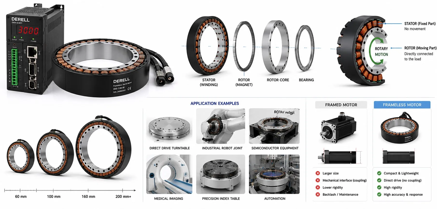
What is a frameless servo motor?
A frameless servo motor gives a machine designer the motor’s working parts without a separate, finished motor housing. The kit centres on a wound stator and a rotating rotor; see how rotor and stator work together. The machine provides their mounting, rotor support and enclosure. Bearings are still required. A suitable design may use the mechanism’s existing bearings to support the rotor as well as the load.
Frameless describes the way the motor is packaged. It does not specify a magnetic flux direction or a guaranteed level of performance. Compare servo motor options against the complete mechanism you need to build.
Three terms worth keeping separate
| Term | Meaning |
|---|---|
| Frameless motor | Motor components built into the machine’s structure. |
| Direct drive | The motor turns the load without a gearbox or belt transmission. |
| Servo drive | The electronics that regulate motor current and execute control loops. |
A frameless kit can drive a load directly or work with a planetary gearbox. Direct drive does not mean integrated drive electronics. You still need a compatible servo drive and suitable feedback. These belong in your review of the complete servo system.
Where does the design earn its place?
Consider a robot joint, a compact rotary stage or a camera positioning assembly. Embedding the motor can remove a duplicate housing and some coupling hardware. A suitable through-bore can also provide a route for cables. Evaluate space and weight at assembly level, including the supporting structure.
Removing a transmission can remove its backlash, but positioning accuracy still depends on the encoder, structural stiffness and control-loop tuning. A frameless kit is no shortcut to precision. If gearing remains necessary, gearbox selection and load and transmission calculations remain part of the job.
What must the machine designer provide?
Mechanical integration: Design rotor retention, bearing support, concentricity and running clearance from the manufacturer’s drawings. Allow for shaft deflection and thermal expansion. There is no universal air-gap or fit tolerance for all kits. Investigate mechanical vibration at its source; tuning cannot repair a poor mechanical fit. Environmental protection comes from the finished enclosure.
Electrical integration: Check motor and drive compatibility, winding data, current limits and feedback interfaces. An absolute encoder, incremental encoder or resolver may suit the application. Optional Hall sensors can provide commutation information; they do not automatically provide precise position measurement. Complete commutation alignment and drive configuration before relying on auto-tuning.
Heat removal: Establish a path from the stator into the machine structure. Peak torque is not a continuous operating rating. Read the cooling and ambient conditions behind the published continuous torque. Treat thermal management as a core motor selection requirement.
A useful calculation: With winding resistance held constant, doubling current produces four times the copper loss: P = I²R. A stationary motor maintaining holding torque can therefore heat up. This relationship describes copper loss, rather than the motor’s total efficiency.