
Calculate load and transmission?
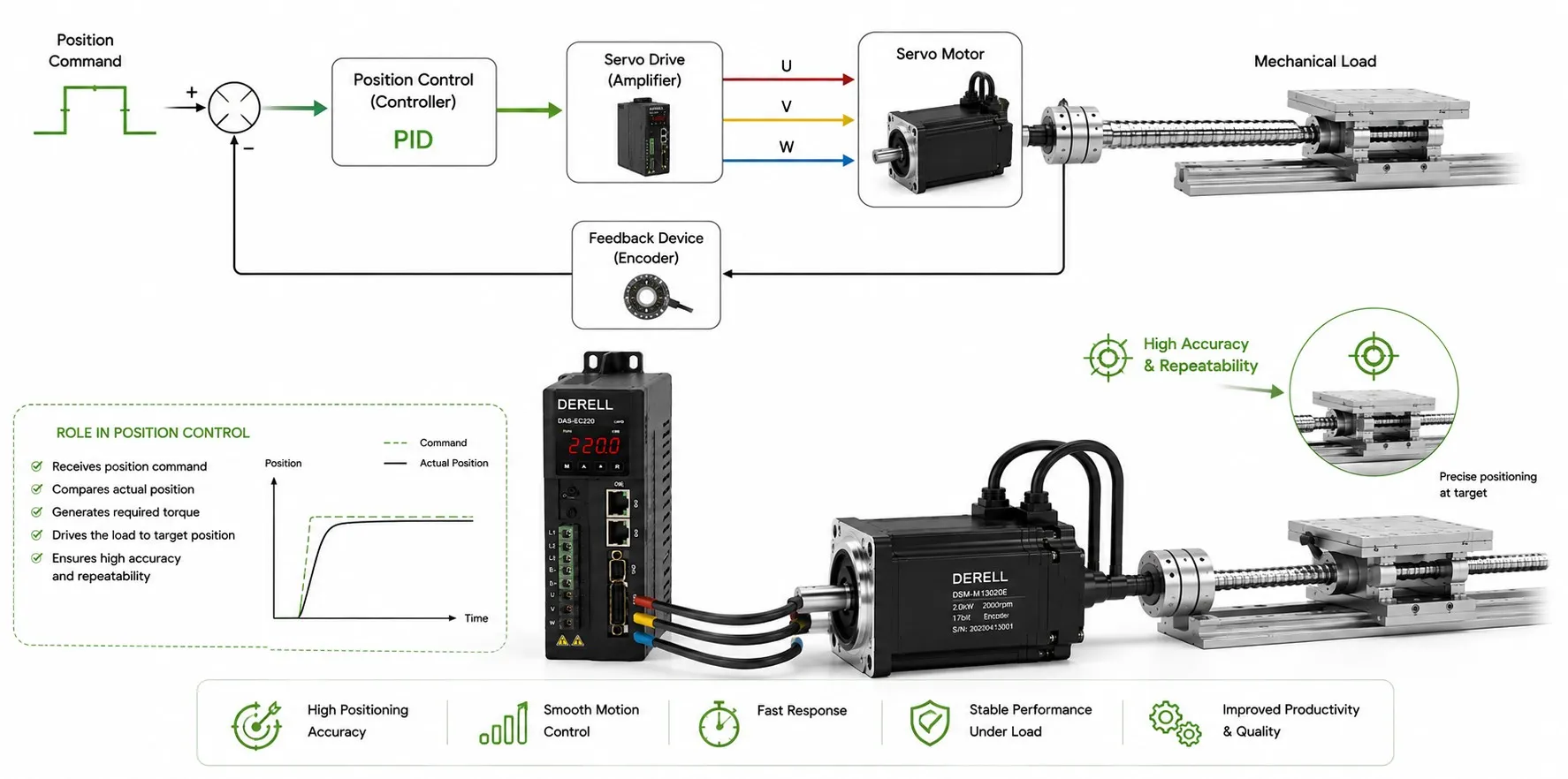
Sizing a servo axis: load torque, speed and gear ratio
A machine can run comfortably at constant speed and still overload its servo during a fast start. To size the axis, establish the load torque, required speed, acceleration and duty cycle first. Then choose a ratio that keeps both the servo motor and gearbox within their operating limits.
Start at the mechanism, not the motor nameplate
Record the total moving mass, travel, target speed, acceleration time, deceleration time and cycle timing. Include the carriage and fixtures, not just the payload. An axis used for precise positioning may have a very different motion profile from one used for steady speed control.
Drum, pulley or pinion: For a tangential force, T = F × r, with force in newtons and radius in metres. A 100 N force acting at a 50 mm radius requires 5 N·m. Using 50 instead of 0.050 introduces a thousandfold error. Our torque guide explains the underlying relationship.
Simple horizontal sliding load: F ≈ μ × m × g + m × a + Fprocess. Upward vertical motion: F ≈ m × (g + a) + Ffriction, where upward acceleration is positive. Use m in kg, a in m/s² and g ≈ 9.81 m/s². A 50 kg mass weighs approximately 490.5 N. For rolling guides, use the manufacturer's resistance data instead of assuming a sliding friction coefficient.
Screw drive: The force-related screw torque is T ≈ F × p / (2π × ηscrew), and screw speed is n = 60 × v / p. Here p is lead in metres per revolution and v is linear speed in m/s. Add the acceleration torque of the screw and other rotating parts. Do not count the same translating mass twice by including its acceleration in both F and an equivalent inertia term.
Use the ratio to translate the output requirements
i = nmotor / noutput
noutput = nmotor / i
Toutput ≈ Tmotor × i × η
Tmotor ≈ Toutput / (i × η)
For 90% gearbox efficiency, enter η = 0.90. The final expression converts an output torque requirement to the motor side; acceleration of the motor rotor and gearbox internals must be added separately. Use actual efficiency data for the chosen planetary gearbox.
| Reduction | Motor speed | Steady motor torque |
|---|---|---|
| 5:1 | 1500 rpm | 4.44 N·m |
| 10:1 | 3000 rpm | 2.22 N·m |
| 20:1 | 6000 rpm | 1.11 N·m |
The largest ratio gives the smallest steady motor torque here, but also requires 6000 rpm. Both the motor and gearbox input must tolerate that speed, and the motor must deliver enough torque there. Check the actual torque-speed curve when matching the motor and drive, then apply the mechanical checks in our gearbox selection guide.
Worked example: the missing starting torque
Consider a rotary axis with 20 N·m resisting torque and 0.08 kg·m² total output-side inertia. It must accelerate from rest to 300 rpm in 0.20 s using a linear speed ramp. Choose a 10:1 reduction and assume 90% efficiency.
Output acceleration: α = (2π × 300 / 60) / 0.20 ≈ 157.08 rad/s².
Output inertia torque: J × α = 0.08 × 157.08 ≈ 12.57 N·m.
Total output torque during acceleration: 20 + 12.57 ≈ 32.57 N·m.
Motor torque to drive that output load: 32.57 / (10 × 0.90) ≈ 3.62 N·m.
Now assume the motor rotor and the gearbox's own input-referred inertia total 0.00030 kg·m². They accelerate at ten times the output acceleration and need another 0.47 N·m. The estimated starting motor torque is therefore 4.09 N·m, compared with 2.22 N·m for the steady output load. These illustrative results include no sizing margin. A final model must account for changing efficiency, no-load losses and the full motion cycle.
Halving the ramp time doubles the inertia-related torque for the same speed change. That is why dynamic performance and speed and torque control need more than a wattage comparison.
Check inertia, peak capability and heating
The ideal reflected load inertia is Jreflected = Jload / i². In this example it is 0.08 / 10² = 0.00080 kg·m². Add the gearbox's own input-referred inertia when evaluating the driven inertia. This geometric relationship does not model transmission losses. The acceptable load-to-rotor inertia ratio depends on the servo and application; there is no single limit for every axis. Auto-tuning cannot compensate for every mechanical mismatch or source of vibration.
Peak torque covers short acceleration and braking demands. RMS torque helps assess the cycle's thermal demand:
TRMS = √[(T₁² × t₁ + T₂² × t₂ + …) / (t₁ + t₂ + …)].
Use motor-shaft torque throughout, including any holding torque during dwell. Check peak torque at the required speed and permitted duration, and RMS torque against the continuous rating adjusted for operating conditions. The servo drive must also provide the necessary current.
Turn the calculation into a usable selection
Check the gearbox's rated torque, acceleration torque limit, input speed, duty cycle, radial and axial loads, backlash and torsional stiffness. A motor capable of torque control does not automatically give the mechanism the required speed and positioning performance. Vertical axes also need an appropriate brake arrangement for holding the load after power removal. Assess the drive's regenerative energy capacity during deceleration.
A useful sizing request includes: a mechanism sketch, total moving mass, radius or screw lead, friction/process force, target speed, acceleration and deceleration times, and the complete cycle including dwell. With these selection parameters, a motor can be sized rather than guessed.
Technical references: Oriental Motor — load torque · load inertia · acceleration and RMS torque · gear ratio and efficiency · Kollmorgen — servo sizing · WITTENSTEIN — gearbox specifications.