
What is output filter?
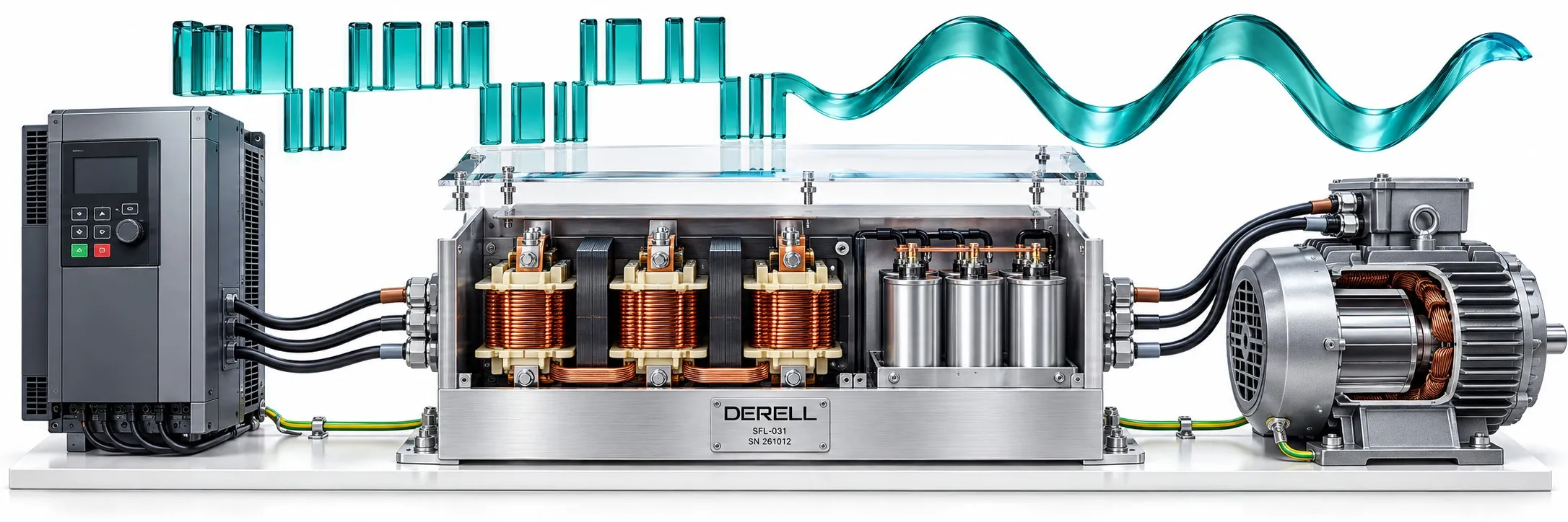
Match the motor-side filter to the actual stress
A VFD output filter sits on the motor side of a variable frequency drive and addresses unwanted effects of power switching. The term covers several devices: load reactors, dV/dt filters, sine-wave filters and common-mode filters. Their functions overlap in places, but they are not interchangeable.
A smooth current can hide a pulsed voltage
An inverter uses PWM switching to produce the required fundamental output frequency. Winding inductance helps smooth the motor current, while the applied voltage can still contain fast pulses. A nearly sinusoidal current does not prove that the terminal voltage is sinusoidal. The carrier frequency describes switching, rather than the frequency that sets motor speed.
dV/dt is the rate of voltage change. An illustrative 600 V transition in 0.2 µs gives 3,000 V/µs. Cable and motor impedance mismatch can create reflected waves and voltage overshoot, adding stress to winding insulation. Cable length matters, but cable characteristics and pulse rise time also influence what reaches the motor.
What each device actually changes
Load reactor: A series inductive element helps limit current changes and cable-charging effects. It does not by itself provide sine-wave voltage. A reactor intended for the supply input is not automatically suitable for PWM output service.
dV/dt filter: Gentler pulse edges and reduced terminal peaks help protect insulation within the filter's specified operating limits. The voltage remains pulsed. Where insulation stress is the main concern, this can be a more compact option than a sine-wave filter.
Sine-wave filter: Typically an LC low-pass network, combining inductors and capacitors, it suppresses switching content to deliver a near-sinusoidal phase-to-phase voltage. Long cable runs and switching-related motor noise are common reasons to consider it. Permitted cable lengths and operating conditions depend on the product.
Common-mode filter: It targets high-frequency currents travelling together on the phase conductors and returning through stray paths. A zero-phase reactor is one available approach. A conventional sine-wave filter does not eliminate every common-mode current or bearing-current problem.
Watch the edges, then the overall waveform
Press Start to draw the three voltage traces. The centre trace retains pulses with gentler edges; the right-hand trace approaches a sine wave. Stop restores the complete comparison. These are teaching sketches, not measurements, a sizing simulation or real filter response times.
Build the selection around operating limits
Collect the drive model, voltage class, motor rated current, overload duty, insulation details, cable type and cable length. Check the filter's minimum and maximum switching frequencies, permitted motor frequency, ambient temperature and cooling requirements. Matching kW ratings alone is insufficient. The drive settings and any output-filter mode must also follow the manufacturer's instructions.
A practical example: A motor 150 metres from its drive does not automatically call for one particular filter. Establish whether the concern is insulation overshoot, acoustic switching noise or common-mode current. The required remedy may be a different filter type or a combination of filtering and installation measures.
Wiring remains part of the solution
Connect the filter between the drive output and the motor. Keep the drive-to-filter connection within the manufacturer's length limit. Follow the specified U/V/W connections, protective earthing, case bonding and broad shield terminations. Route motor wiring away from PLC, sensor and encoder circuits. Change the shielding arrangement only where the selected system's documentation permits it.
If electromagnetic interference or drive faults persist, inspect cable routing, shield connections and motor insulation. A filter is one part of the diagnosis. Adding a motor-side filter does not establish whole-system EMC emission compliance; the applicable drive standards and installation requirements still apply.
Related reading
References
Danfoss: Output Filters Design Guide; TDK: EMC Output Filter Solutions; TE Connectivity / Schaffner: Load Reactors; Schneider Electric: dV/dt and motor insulation; Schneider Electric: power-factor correction capacitors.