
What is harmonic filter?
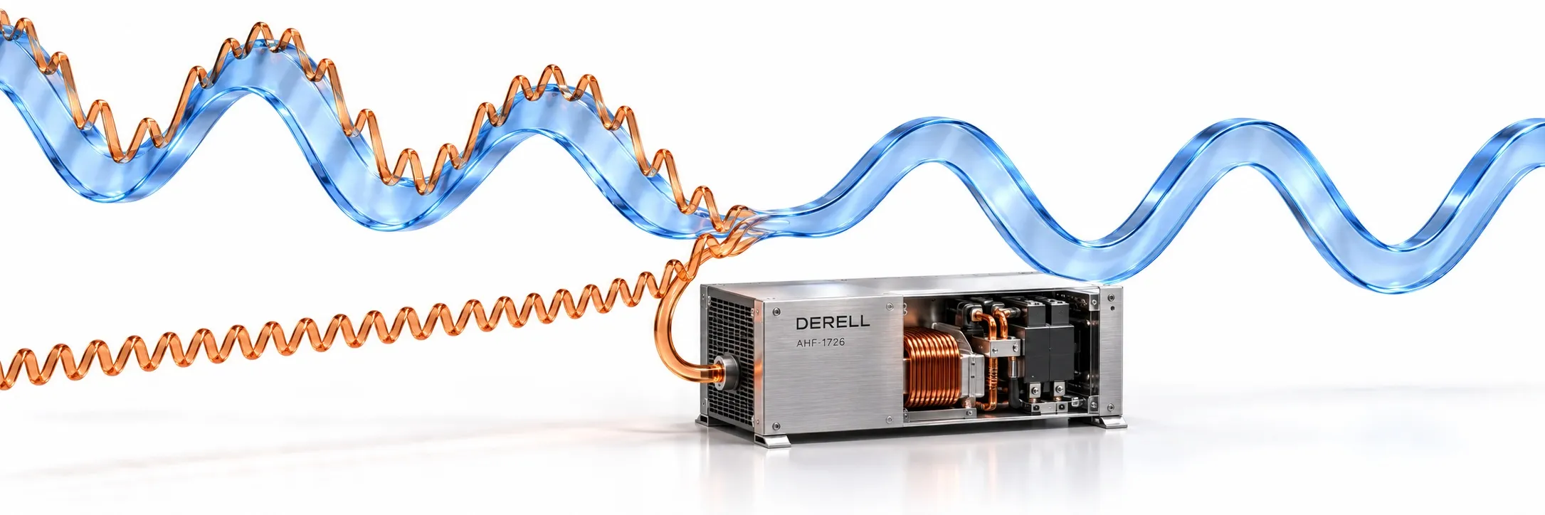
Cleaner supply current starts with identifying the distortion
A harmonic filter reduces selected current or voltage components at integer multiples of the fundamental frequency. In a power installation, the practical objective is to limit extra losses, overheating and distortion reaching other equipment. A filter is chosen for a measured problem; fitting one to every installation is not automatically necessary or beneficial.
With a 50 Hz supply frequency, the third harmonic is 150 Hz, the fifth is 250 Hz and the seventh is 350 Hz. These are frequency components of current or voltage, rather than separate “high-frequency powers”. Components that are not integer multiples are treated separately as interharmonics.
Look at how the load draws current
A resistor supplied by a sinusoidal voltage draws a similar current waveform. Rectifier inputs in variable-frequency drives, some UPS systems and electronic power supplies can draw current in pulses. Such nonlinear loading introduces current harmonics. Those currents flowing through supply impedance can also distort the voltage seen by other loads on the same bus.
A conventional three-phase six-pulse rectifier has characteristic orders of 5, 7, 11 and 13. In four-wire systems supplying phase-to-neutral nonlinear loads, the third, ninth and fifteenth harmonics can add in the neutral. The circuit arrangement and measured spectrum determine which issue needs attention; third-harmonic mitigation is not the answer to every drive problem.
Connect the waveform to its harmonic spectrum
The example below keeps the fundamental unchanged. Initially, the fifth and seventh components are 20% and 12% of the fundamental; after the assumed filtering, they are 4% and 2.4%. The dashed grey curve is the fundamental sine wave. Moving markers compare the same instant in both waveforms.
Current THD uses the RMS values of the harmonic components: THDi = √(I₂² + I₃² + …) / I₁ × 100. Assuming no harmonics other than the fifth and seventh, the example gives √(20² + 12²) = 23.3% before filtering and √(4² + 2.4²) = 4.7% afterwards. This is a teaching model, not a product performance claim. Harmonic phase angles also influence waveform shape.
Three approaches, with different design requirements
Passive filtering uses inductors and capacitors to create a frequency-dependent network. A tuned shunt branch can provide a low-impedance path for a selected harmonic, while series and broadband arrangements operate differently. A tuned filter is a passive-filter design, not an independent category that is always more accurate or effective. Performance depends on supply impedance and operating load.
An active harmonic filter measures load current and generates an opposing compensating current for the targeted components. Typically connected in parallel with the bus, it can serve changing loads or several loads together. Its power stage uses devices such as IGBTs. Required compensating amperes, harmonic orders and operating limits matter more than a motor kW rating alone.
Hybrid filtering combines active and passive elements. A custom-engineered solution still uses one or more of these principles; “custom” does not describe a separate filtering mechanism or guarantee the best result.
A detuned capacitor bank has a specific purpose
A reactor placed in series with a power-factor-correction capacitor helps control resonant amplification and protects the capacitor from harmonic stress. That does not establish a guaranteed installation-wide THD value. Select the reactor and capacitor as a coordinated assembly. Adding capacitance without checking the network can make an existing harmonic problem worse.
Supply-side distortion and motor-side filtering are different jobs
A line reactor or DC-link choke can reduce distortion associated with a rectifier input, but it does not necessarily achieve the performance of a dedicated harmonic-filter system. A zero-phase reactor, EMI filter or RFI filter primarily addresses different interference mechanisms.
Likewise, a motor-side output filter or output reactor is selected for its specified output-side function. Insulation stress, dV/dt and effects associated with carrier frequency require their own assessment. Identify which side of the drive needs treatment before selecting a component.
Measurements that make a filter specification useful
Record THDi and THDv separately, together with the spectrum, fundamental current, operating load range and measurement location. Include transformer or generator data and existing capacitor stages. At light load, a small fundamental-current denominator can produce a large THDi percentage; the actual harmonic current in amperes remains essential.
IEEE 519-2022 addresses performance at the installation’s point of common coupling (PCC). Current TDD refers harmonic current to a defined maximum-demand current rather than the instantaneous fundamental current. Equipment-terminal THDi therefore cannot simply be compared with a facility TDD limit. A blanket “5% is acceptable everywhere” rule is unsuitable.
References
ABB: harmonics and mitigation methods
ABB: drives with passive filters
Schneider Electric: detuned reactors
Schneider Electric: total demand distortion