
What is Conductive encoders?
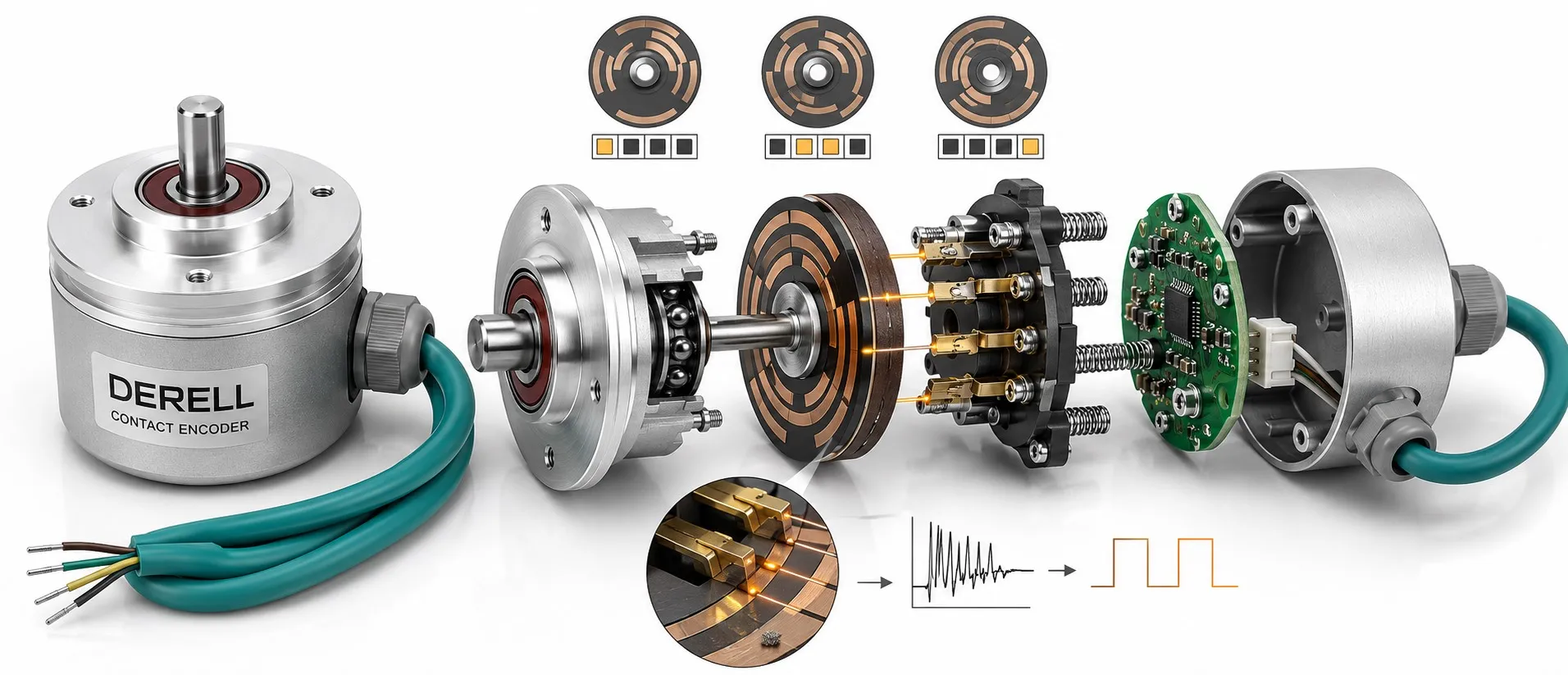
Contact encoders: turning a patterned disk into digital signals
A contact encoder, sometimes described as a conductive encoder, reads a pattern through sliding electrical contacts. Conductive tracks make a connection; insulating sections interrupt it. The receiving circuit turns those changes into digital states. It is a simple way to connect physical movement with the basic purpose of an encoder: producing information a controller can read.
Follow one contact all the way to the counter
Imagine an ordinary switch operated by a rotating pattern. In this example, four metal sectors connect to the inner common ring C. The fixed A contact reaches each sector in turn. On metal, A connects to C; on insulation, the circuit opens. No spark is needed to generate a signal: the circuit detects a low-current contact making or breaking.
Why does closing the contact produce a zero?
The illustrated pull-up resistor holds the input HIGH, or 1, while the contact is open. Closing the contact connects it to 0 V through C, making the input LOW, or 0. The example counter increments on each falling edge. A different circuit can reverse the logic, so match the receiver to the actual output arrangement.
Four equally spaced sectors create four pulse cycles per revolution: 4 PPR. The spacing between equivalent events is 90 mechanical degrees. That describes this example's resolution, rather than guaranteeing its accuracy. Faster rotation raises the pulse frequency, which the high-speed counter and its filter must accommodate.
The contact method does not determine the position format
An incremental encoder reports movement through pulses. Separate A and B signals can also identify direction. An absolute encoder presents a position code; suitable multiple-track patterns can use Gray coding. Either approach can involve contacts. The single channel in the animation cannot independently identify direction or the absolute angle at power-up.
A potentiometer can also have a sliding contact, but its circuit measures a changing resistance or voltage. Here, the useful information is open versus closed. Keep that distinction in mind when comparing an analog encoder or selecting an analog input.
When one movement creates several unwanted edges
A real contact can briefly open and close during a transition. This is contact bounce, and a sensitive counter can interpret it as several movements. Debouncing uses hardware or software to reject these short transitions. Filtering suitable for a slowly operated knob may suppress legitimate pulses from a faster shaft. Set a PLC or encoder interface using the device's timing requirements.
Choose for the operating conditions
Menu navigation, setting knobs and stepped user controls are familiar contact-encoder applications. Compare optical and magnetic designs for continuous motion sensing. Read the specified shaft speed, contact voltage/current, rotational life and IP rating; the sensing principle alone does not establish suitability.
Before connecting bare contacts to a 24 V input, verify their ratings. TTL and HTL interfaces and line driver outputs can require different receiver circuits. Cable length, shielding and electromagnetic interference also matter. An interference filter does not automatically eliminate mechanical bounce.
Do not treat sanding or an arbitrary cleaning spray as routine maintenance. Either can damage contact coatings or materials. Check connectors, wiring, filter settings and mechanical play first; follow the manufacturer's servicing instructions. A worn sealed part may need replacement. Select suitable mounting accessories, counters and encoder products for the complete application.