
What feedback options are available in DC drives?
What feedback options are available for DC drives?
A speed command tells a drive what the machine should do. Feedback tells it what is actually happening. If a conveyor encounters a heavier load, for example, its motor may begin to slow down. A closed-loop controller uses the difference between requested and actual speed to adjust the motor’s output.
There is more than one way to obtain that information. A DC drive may use a shaft-mounted sensor, estimate speed from electrical measurements, or combine several measurements in separate control loops. Speed, position, armature current and field current describe different aspects of operation. Choosing feedback starts with deciding which of these the application needs to control.
Understand which control loop needs the measurement
In a typical closed-loop speed system, the speed controller produces a torque or current demand. A faster inner current controller then regulates armature current to meet that demand. The speed sensor and current measurement therefore work together rather than compete as alternative solutions.
A positioning system adds another requirement: knowing where the mechanism is and controlling its movement toward a target. This may involve a position loop in the drive or an external motion controller. Merely connecting an encoder does not give every drive positioning capability. The supported control methods must match the job.
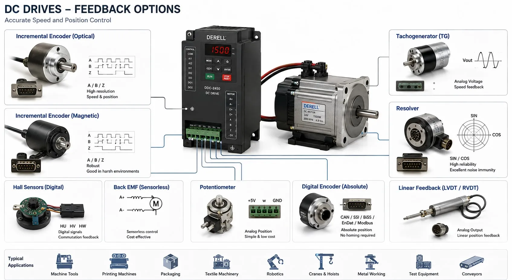
Encoders: digital information from shaft movement
An incremental rotary encoder produces signals as its shaft turns. With compatible A and B channels, the controller can determine movement and direction. Counting movement over time, or measuring the interval between pulses, allows speed to be calculated. An optional Z channel normally provides a reference mark once per revolution.
Incremental position is relative to an established reference. A conventional incremental encoder does not independently report its absolute position after power is restored. An absolute encoder provides coded position information, but it requires a compatible electrical interface and communication format. These devices should not be treated as interchangeable accessories.
Selection involves more than resolution. Supply voltage, output circuit, cable length, maximum input frequency and mechanical mounting all matter. Increasing the pulse count also increases signal frequency at a given speed. Low-speed performance depends on the measurement method and controller settings as well as the number of pulses.
Tachogenerators: a direct analog speed signal
A tachogenerator is mechanically coupled to the motor and generates an electrical signal related to speed. For a conventional DC tachogenerator, voltage magnitude indicates rotational speed and polarity indicates direction. The drive compares this signal with its speed reference.
This is a continuous feedback device, not the handheld tachometer used during a maintenance check. Its voltage-per-speed rating must match the drive’s input range and scaling. Coupling problems, brush wear and electrical noise can affect the signal and produce irregular speed control.
Tachogenerator feedback remains relevant when maintaining existing machinery. During a retrofit, compatibility and the condition of the complete feedback assembly deserve attention alongside the choice of replacement drive. The installation’s maintenance requirements include the sensor and coupling, not just the power electronics.
Resolvers: angle feedback with a dedicated interface
A resolver is an electromechanical angle sensor. When excited correctly, it produces signals with sine and cosine relationships to shaft angle. Suitable electronics decode the angle and can calculate speed from its change over time. Resolver designs can be useful in demanding temperature and vibration environments.
However, resolver support is not universal among DC drives. An appropriate option card, conversion electronics or external controller may be required. Mechanical robustness alone does not establish compatibility; excitation requirements and the receiving interface must also match. This is an important distinction when comparing motor feedback sensors.
Speed estimation without a shaft sensor
A rotating DC motor generates back electromotive force, commonly called back EMF. A drive can use electrical measurements and a motor model to estimate this quantity and infer speed. With approximately constant magnetic flux, back EMF is approximately proportional to speed.
A simplified steady-state relationship is E ≈ Va − IaRa: back EMF is estimated from armature voltage after allowing for the resistive voltage drop. This simplified expression omits brush voltage drop and transient inductive effects. Practical estimation must account for the relevant motor behavior.
Terminal voltage is therefore not a direct speed measurement. Changing load current, winding temperature or field flux can affect the estimate. At very low speed, the small back EMF makes accurate estimation more difficult. Whether this approach is sufficient depends on the application’s speed range and regulation requirements.
The term sensorless usually means that no shaft-mounted speed sensor is used. Electrical measurements still take place inside the drive. It should not be interpreted as a promise of accurate absolute position measurement.
Armature current feedback: controlling torque production
For a DC motor, electromagnetic torque can be described approximately by T ≈ k · Φ · Ia. If magnetic flux Φ remains constant, torque is approximately proportional to armature current. When the field is weakened, the same current no longer produces the same torque.
Current feedback supports current regulation, torque control and current limiting. Many industrial drives measure armature current internally, so an external current transducer is not automatically needed. The measurement is also not a direct reading of usable shaft torque: motor losses and operating conditions affect the relationship.
The interaction between current regulation and speed regulation helps determine the machine’s dynamic response. A high-resolution speed sensor cannot compensate for every limitation elsewhere in the control system.
Field feedback: managing motor excitation
Separately excited motors have a field winding whose current establishes the magnetic field. Monitoring and regulating this current supports excitation control, field weakening and field-loss detection. Field current does not directly measure shaft speed, and magnetic saturation means its relationship with flux is not always linear.
Field voltage provides different information. Voltage may be present even when the required current is not flowing through the winding. Consequently, field voltage and field current should not be treated as equivalent feedback signals. Permanent-magnet DC motors have no field winding and do not require this excitation loop.
Combining feedback and handling signal failure
A drive may simultaneously use encoder speed, armature current and field current. Some machines also measure motion at the load, separately from the motor, to account for transmission effects such as backlash or compliance. Such arrangements require a control architecture that supports the additional measurement.
More sensors do not automatically create a redundant or safety-rated system. What happens after a missing or implausible signal depends on the drive’s capabilities and configuration. A fault stop or a change to estimated speed may be available, but neither behavior should be assumed. Feedback-loss behavior must suit the machine and its protective functions.
A PLC can receive speed and status data without running the drive’s fast feedback loops itself. When planning PLC integration, establish where each measurement is processed and which device closes each control loop.