
What are the operating principles of DC drives?
How do DC drives work?
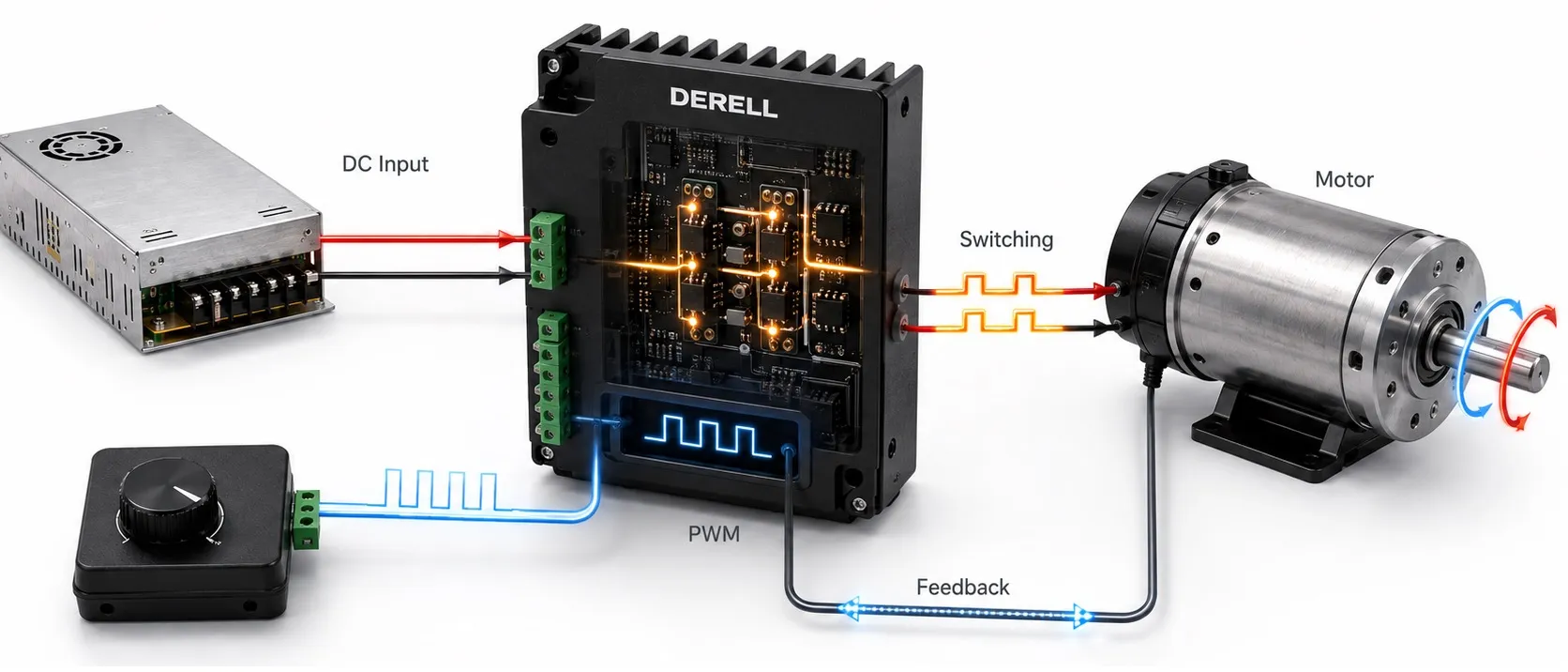
A DC drive turns a speed or torque command into controlled electrical power for a motor. Its power stage supplies the required voltage and current, while its control circuits decide how that output should change. Suitable designs also manage reversing and electrical braking.
The explanation below concerns conventional brushed DC motors. Brushless DC motors require a different electronic commutation arrangement. An AC variable frequency drive and a servo system may share control concepts with a DC drive, but the motor and power-conversion requirements must still match.
Follow a speed command through the system
Imagine a conveyor commanded to run at a steady speed. The reference may come from a potentiometer, an operator panel or a PLC. The drive receives it through an analog input, digital commands or a supported communication interface.
If the load increases and the conveyor begins to slow, a closed-loop speed controller detects the difference between reference and actual speed. It requests more motor torque, usually by increasing the armature-current demand. The power stage then changes its output to produce the requested current within the configured limits.
The command carries information; the power stage carries motor power. In a typical PLC-controlled installation, the PLC coordinates the machine while the drive executes the fast motor-control loops.
Why voltage influences speed and current influences torque
As a DC motor rotates, it generates a voltage called back electromotive force, or back EMF. With approximately constant field flux, this voltage is approximately proportional to rotational speed.
A simplified steady-state relationship is Va ≈ E + IaRa. The applied armature voltage must balance back EMF and the resistive voltage drop in the armature. This simplified expression leaves out brush voltage drop and transient inductive effects.
Increasing armature voltage generally allows a higher operating speed, but load current changes the internal voltage drop. Consequently, a fixed voltage does not guarantee exactly the same speed under every load. Accurate regulation usually requires suitable speed feedback or an appropriate estimation method.
Electromagnetic torque follows approximately T = k × Φ × Ia, where Φ represents magnetic flux. At constant flux, torque is approximately proportional to armature current. This relationship explains why current regulation is central to torque control.
Two common ways to produce adjustable DC output
Controlled rectification: Many industrial DC drives operate from an AC supply through a thyristor bridge. The controller changes the firing angle, determining when the thyristors begin conducting within the supply waveform. This adjusts the average DC output voltage.
The resulting output can contain substantial ripple. Motor inductance and, where required, additional reactors help smooth the current. The bridge arrangement also affects which directions of voltage, current and power flow are supported. Different DC converter types therefore offer different operating capabilities.
PWM conversion: A transistor-based drive switches a DC supply through power devices such as MOSFETs or IGBTs. With pulse-width modulation, the switching pattern regulates the voltage waveform applied to the motor. Motor current can continue through designed recirculation paths between switching intervals because the winding is inductive.
For an ideal arrangement that applies either 0 V or 24 V across the motor, a 50% duty cycle gives a 12 V average. It does not guarantee half the maximum motor speed. Load and motor characteristics still matter, and other bridge-modulation strategies have different duty-cycle relationships.
An AC inverter drive may also use PWM, but it synthesizes the phase outputs needed by its motor. Sharing a modulation technique does not make AC and DC motor drives interchangeable.
Current and speed loops perform different jobs
In a common control arrangement, the speed loop generates a current or torque reference. A faster inner current loop then adjusts the converter to achieve that reference. This division lets the drive react to electrical changes while controlling the slower mechanical response.
At startup, back EMF is low, so current must be controlled. The current limit also restricts available torque. If the load needs more torque than the permitted current can produce, the motor may accelerate more slowly than requested or fail to reach the target.
Field control extends the operating range
A separately excited motor uses a field winding to establish magnetic flux. Below base speed, the field is commonly kept approximately constant while armature voltage is adjusted. Once the available armature voltage reaches its limit, suitable motors can run faster through field weakening.
Reducing flux also reduces torque per ampere. Within the permitted operating envelope, this can provide an approximately constant-power region above base speed. Mechanical speed limits and commutation requirements still apply.
Loss of excitation is a fault condition rather than a normal speed command; under some conditions it can cause dangerous acceleration. A conventional permanent-magnet DC motor has no adjustable field winding, so this field-control method is unavailable.
Reversing requires control of relative polarity
Torque direction depends on the relative directions of field flux and armature current. Reversing one while retaining the other reverses torque. Reversing both does not reverse torque. With a permanent-magnet motor, the fixed field means direction is controlled through the armature.
A suitable transistor H-bridge can apply the required output polarity. Industrial thyristor systems may use an appropriate reversing-converter arrangement. A reverse command is a controlled operating sequence, not an instruction to swap live motor leads. Current, deceleration and acceleration must remain within the system’s capabilities.
Four-quadrant operation means motoring and electrical braking are possible in both directions of rotation. Whether energy can also be returned to the upstream supply depends on the complete power circuit.
Feedback and ramps shape the movement
An encoder provides movement information, while a tachogenerator produces an analog signal related to speed. Some drives estimate speed from electrical measurements. An encoder alone does not establish position control; the drive or motion controller must also implement the necessary position loop.
Acceleration and deceleration ramps usually shape the speed reference. The current and voltage outputs then change as needed to follow that reference. Describing this only as gradually increasing voltage misses the action of the control loops and their limits.
Controller tuning influences overshoot and oscillation. Excessively aggressive loop gains can excite mechanical resonances rather than improve useful response. Feedback quality, transmission stiffness and load inertia all contribute to the result.
Braking is also an energy-management problem
During deceleration, the motor can act as a generator. In resistor-based dynamic braking, generated energy is dissipated as heat in a correctly designed braking-resistor circuit. In regenerative braking, it is returned to a supply capable of accepting it.
Neither function should be assumed available on every drive. A DC source that supplies power may be unable to absorb returned energy. Similarly, a resistor cannot be attached arbitrarily to any converter output.
The DC injection braking used with some AC motor drives is a different operating method. Electrical braking also does not automatically replace a mechanical brake needed to hold a load when power is removed.
Protection and the connection to VFD and servo control
Current, temperature, field status and feedback validity may be monitored to detect abnormal operation. External fuses and other protective devices must suit the converter and installation. A normal stop command is not electrical isolation.
Related current and speed-control principles also appear in vector-controlled VFDs and servo motor systems. The differences lie in motor construction, how the required currents are produced and which motion functions are supported. Selection should follow the actual load and control requirements.