
VF-S11 toshiba inverters
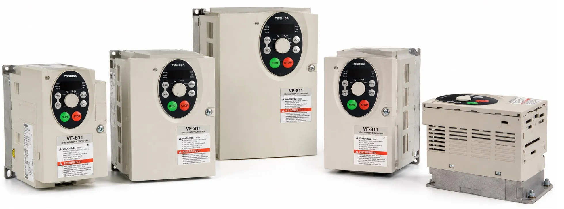
Toshiba TOSVERT VF-S11 AC Drive is one of Toshiba's important compact inverter platforms, combining advanced motor control, flexible programmable I/O, regenerative braking capability and industrial communication options in a relatively small enclosure.
The VF-S11 series was produced from 2003 to 2013. After discontinuation, Toshiba identified the VF-S15 as the recommended successor. However, a large installed base of VF-S11 drives remains in industrial machines, so manuals, parameter information, replacement drives and fault diagnosis are still important for maintenance work.
The VF-S11 is considerably more than a basic V/f inverter. It provides sensorless vector control, auto-tuning, PID control, energy-saving functions, preset speeds, regenerative braking support, flexible analog / digital I/O and several industrial communication options.
VF-S11 Power and Supply Classes
The VF-S11 family was produced for several supply-voltage classes. Single-phase 200–240 V models cover approximately 0.2–2.2 kW, while three-phase 200–240 V and 380–500 V models extend up to approximately 15 kW. Versions for 525–600 V supplies were also produced.
Common models found in existing machines include VFS11S-2004PL, VFS11S-2007PL, VFS11S-2015PL and VFS11S-2022PL, together with 400 V class models such as VFS11S-4007PL, 4015PL, 4022PL, 4037PL, 4055PL, 4075PL, 4110PL and 4150PL.
Motor Control Performance
The VF-S11 supports constant V/f, variable-torque V/f, automatic torque boost, sensorless vector control, automatic energy-saving control, dynamic energy-saving control for fan and pump applications, and PM motor control in suitable applications.
Toshiba specified more than 200% starting torque as one of the important VF-S11 performance characteristics. With correct motor data and sensorless vector control, the drive can provide strong low-speed torque and improved speed stability when mechanical load changes.
When vector control is used, motor rated current, rated speed and other motor constants should be entered correctly. If a non-standard motor is connected, auto-tuning is particularly important for obtaining stable low-speed performance.
Up to 500 Hz Output and 16 kHz PWM Carrier Frequency
The VF-S11 supports output frequencies up to approximately 500 Hz, allowing use in standard machinery as well as certain high-speed motor applications such as spindle or woodworking systems.
PWM carrier frequency can be adjusted up to 16 kHz. A higher carrier frequency can reduce audible motor noise, but inverter temperature, ambient conditions and output-current derating must also be considered.
VIA Analog Input – 0–10 V and 4–20 mA
VIA is a multifunction programmable analog input. Its standard configuration can be used for a 0–10 VDC frequency reference. When the VIA V/I selector is switched to the current-input position, the terminal can be configured for 4–20 mA or 0–20 mA operation.
The VIA input impedance is approximately 30 kΩ in voltage mode and approximately 250 Ω in current mode. Standard industrial signals from PLCs, process controllers and transmitters can therefore be used directly as frequency-reference signals.
VIB Analog Input
VIB is another analog input and can be used for a 0–10 VDC reference. An external frequency potentiometer can be connected using the PP – VIB – CC terminals.
The availability of VIA and VIB allows more advanced control arrangements, including switching between two analog references or using one input as a process reference and the other as PID feedback.
Using VIA and VIB as Digital Contact Inputs
One of the unusual VF-S11 hardware features is that the VIA and VIB analog terminals can also be configured as programmable digital contact inputs. Their analog / contact-input behaviour is selected through parameter F109.
When these terminals are used as contact inputs with sink / NPN logic, a 4.7 kΩ / 0.5 W resistor must be installed between P24 and the applicable VIA or VIB terminal. When VIA is used as a contact input, the VIA selector must be placed in the V position.
Important: Do not wire VIA or VIB as contact inputs before confirming the analog / digital configuration and required resistor. Incorrect configuration can cause an input to remain permanently active or can result in improper operation of connected control equipment.
Sink / Source Control Logic
VF-S11 digital control circuitry supports sink and source logic, allowing integration with PLC systems that use NPN or PNP output structures.
The control-terminal system includes programmable inputs such as F, R, RES, S1, S2 and S3, together with CC, PLC and P24 auxiliary terminals.
F, R and RES Control Terminals
F is normally used for forward operation and R for reverse operation in the standard configuration. Their functions can be reassigned through the programmable terminal parameters.
RES does not disable the protection system. The RES terminal is used as a trip-reset command. When the drive is in a trip condition, the reset command can clear the trip after the original fault condition has been removed.
Resetting a trip does not repair the cause of the fault. If overcurrent, overvoltage, motor insulation failure or mechanical seizure is still present, the VF-S11 will trip again.
S1, S2 and S3 Programmable Inputs
S1, S2 and S3 are programmable digital inputs. In typical applications they can be used for preset-speed selection, but the VF-S11 terminal architecture allows many other functions to be assigned.
With the appropriate terminal assignments, up to 15 preset operating frequencies can be selected using digital input combinations. This allows multiple motor speeds to be called without requiring an analog PLC output.
FM Analog Monitor Output
FM is the multifunction programmable analog monitor output. The standard assignment is output-frequency monitoring, but parameter settings allow other internal drive values to be sent to an external meter or PLC analog input.
The FM terminal can operate in voltage / meter mode or, with the FM selector in the current-output position, can be configured for 0–20 mA or 4–20 mA output. In current mode the connected load resistance should be approximately 750 Ω or less.
RY-RC, OUT-NO and FLA-FLB-FLC Outputs
The VF-S11 provides more than a simple fault relay. RY-RC and OUT-NO can be assigned to functions such as low-speed detection, frequency attainment, run status or other internal conditions.
Two functions can be assigned to the multifunction output channels, allowing AND / OR logic combinations to be used. FLA-FLB-FLC provides a programmable relay contact and is commonly used to send protection or trip status to an external control system.
The OUT-NO channel can also be configured as a pulse-train output over an approximate 38–1600 Hz range. This is not a real motor-encoder feedback output; it is a programmable pulse representation of a selected internal drive value.
PID Process Control
The VF-S11 includes built-in PID control. The drive can compare a process reference against analog feedback and automatically adjust motor speed for pump, fan, pressure, flow and similar process applications.
P, I and D gains can be adjusted separately. For example, VIB may be used for the process reference while VIA receives a 4–20 mA or 0–10 V feedback signal.
Energy-Saving Functions for Fans and Pumps
The VF-S11 automatic energy-saving mode monitors the motor load and adjusts excitation to reduce unnecessary motor losses. Dynamic energy-saving control is also available for variable-torque fan and pump applications.
These functions make the VF-S11 suitable not only as a machine drive but also as a compact process-control inverter.
Auto-Tuning and Motor Parameters
Automatic torque boost, sensorless vector control and energy-saving functions can be combined with motor auto-tuning. During auto-tuning the VF-S11 identifies important motor electrical characteristics and adapts its control algorithm to the connected motor.
Correct motor nameplate data becomes particularly important when the motor rating differs from the inverter rating, when a long motor cable is used or when the motor is not a standard Toshiba induction motor.
Sensorless vector control is intended for individual motor control. Running several motors in parallel from one inverter is not suitable when accurate vector-control performance is required.
DC Braking and External Braking Resistor
The VF-S11 provides DC injection braking for motor stopping and holding applications. For rapid deceleration or regenerative loads, an external dynamic braking resistor can also be used.
External braking resistors are connected through the appropriate PA / PB braking terminals. Resistance and power ratings must be selected according to the exact VF-S11 model rather than motor kW alone.
Applications such as cranes, high-inertia machinery, presses or continuously regenerative loads require the total regenerative energy and operating duty cycle to be considered when selecting the braking resistor.
RS485, Modbus RTU, DeviceNet, LonWorks and CC-Link
The VF-S11 communication platform was advanced for its generation. Optional RS485 / Modbus RTU, DeviceNet, LonWorks and CC-Link interfaces were available.
For RS485 communication, Toshiba provided external converter units RS4001Z / RS4002Z and the internal RS4003Z communication board. DeviceNet uses the DEV001Z option, while VF-S11 CC-Link communication is associated with the CCL002Z option.
Through serial communication, a supervisory controller can read operating data, issue frequency and RUN / STOP commands, and read or modify supported parameters.
Built-In EMC / Noise Filter
Many VF-S11 240 V and 380–500 V models include a built-in noise / EMC filter. Toshiba documentation distinguishes these from some 600 V versions where an internal filter is not provided.
EMC performance depends on the complete installation, not only on the inverter filter. Correct grounding, shielded motor cable, separation of power and control wiring, and suppression of contactor coils are also important.
Side-by-Side Panel Installation
VF-S11 drives were designed to support compact side-by-side panel installation, helping reduce cabinet space. Cooling requirements must still be respected.
When close mounting is used, ventilation restrictions and ambient temperature must be considered. If cabinet temperature becomes excessive, spacing or output-current derating may be required. Airflow above and below the inverter must not be blocked.
VF-S11 Protection and Fault Diagnosis
The VF-S11 monitors a wide range of electrical and mechanical conditions including acceleration, deceleration and constant-speed overcurrent; input and output phase loss; overvoltage; inverter and motor overload; braking-resistor overload; over-torque; overheating; low current; undervoltage; ground fault; external thermal protection and option-board faults.
The fault system is designed not only to stop the inverter but also to indicate the operating condition in which the fault occurred. For example, OC1 / OC2 / OC3 identify overcurrent during acceleration, deceleration or constant-speed operation, while OP1 / OP2 / OP3 distinguish overvoltage in those same operating regions.
For this reason, a VF-S11 trip should be diagnosed according to both the displayed code and the machine operating condition at the moment the trip occurred.
Why the VF-S11 Is Still Important
Although the VF-S11 has been discontinued, it remains installed in many machines built during the 2000s and early 2010s. Maintenance work may therefore require reading the original parameters, interpreting the correct fault code, locating a temporary replacement or migrating the machine to a newer inverter platform.
The VF-S15 is Toshiba's recommended successor, but replacement should never be based only on matching kW. Supply voltage, motor current, terminal assignments, VIA/VIB analog configuration, communication options, braking resistor, motor-control mode and existing parameter logic must also be reviewed.
Service note: Before working on VF-S11 power or control wiring, disconnect the incoming supply and wait for the DC bus to discharge. Toshiba service documentation requires confirming that the charge indication is OFF and that the DC bus has fallen to a safe level before touching internal terminals.
VF-S11 technical resources:
+ Toshiba VF-S11 User Manuals, Communication Manuals and Technical Files
+ Toshiba VF-S11 Fault Codes and Troubleshooting
+ Toshiba VF-S15 – Recommended Successor to VF-S11
+ Toshiba VFD Contact Information
+ Toshiba Drives Main Page
+ AC Drive / VFD Main Page
Refine Search

VFS11S-4007PL
VS-S11 Toshiba motor inverter 0.75 kw output power, 380 Volt main source, 2.3 Amper Toshiba VF..
650.00USD Ex Tax: 650.00USD

VFS11S-4015PL
VS-S11 Toshiba motor inverter 1.5 kw output power, 380 Volt main source, 4.1 Amper Toshiba VFD..
700.00USD Ex Tax: 700.00USD

VFS11S-4022PL
VS-S11 Toshiba motor inverter 2.2 kw output power, 380 Volt main source, 5.5 Amper Toshiba VFD..
750.00USD Ex Tax: 750.00USD

VFS11S-4055PL
VS-S11 Toshiba motor inverter 5.5 kw output power, 380 Volt main source, 14.3 Amper Toshiba VF..
850.00USD Ex Tax: 850.00USD

VFS11S-4150PL
VS-S11 Toshiba motor inverter 15 kw output power, 380 Volt main source, 33 Amper Toshiba VFD d..
930.00USD Ex Tax: 930.00USD
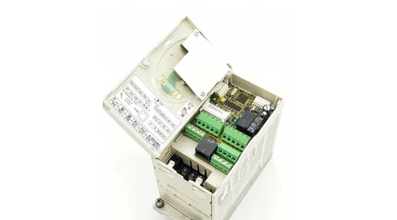
VFS11S-2004PL
VS-S11 Toshiba motor inverter 0.4 kw output power, 220 Volt main source, 3.3 Amper Toshiba VFD..
222.00USD Ex Tax: 222.00USD

VFS11S-2007PL
VS-S11 Toshiba motor inverter 0.75 kw output power, 220 Volt main source, 4.8 Amper Toshiba VF..
154.00USD Ex Tax: 154.00USD
VFS11S-2015PL
VS-S11 Toshiba motor inverter 1.5 kw output power, 220 Volt main source, 8.0 Amper Toshiba VFD..
188.00USD Ex Tax: 188.00USD
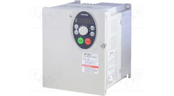
VFS11S-2022PL
VS-S11 Toshiba motor inverter 2.2 kw output power, 220 Volt main source, 11.0 Amper Toshiba VF..
235.00USD Ex Tax: 235.00USD

VFS11S-4037PL
VS-S11 Toshiba motor inverter 4 kw output power, 380 Volt main source, 9.5 Amper Toshiba VFD d..
800.00USD Ex Tax: 800.00USD

VFS11S-4075PL
VS-S11 Toshiba motor inverter 7.5 kw output power, 380 Volt main source, 17.0 Amper Toshiba VF..
900.00USD Ex Tax: 900.00USD
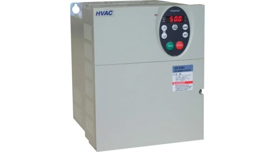
VFS11S-4110PL
VS-S11 Toshiba motor inverter 11 kw output power, 380 Volt main source, 27.7 Amper Toshiba VFD..
920.00USD Ex Tax: 920.00USD