
Toshiba VF-S11 fault code
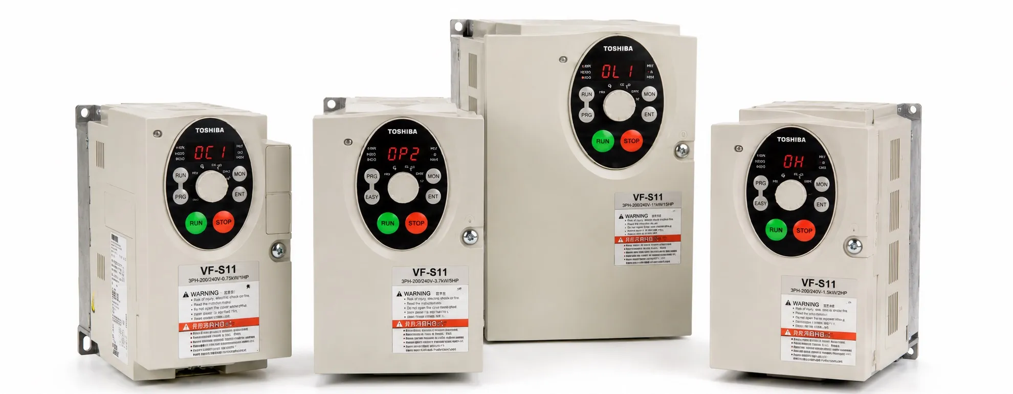
Toshiba VF-S11 Fault Codes and Troubleshooting
When a Toshiba VF-S11 trips because of an electrical, motor or mechanical fault, do not immediately reset the inverter. Identify and remove the original cause first. Resetting a drive while an overcurrent, overvoltage, motor insulation fault or mechanical problem is still present will normally cause another trip and may place additional stress on the power stage.
After the fault condition has been corrected, the VF-S11 can be reset by cycling the incoming power, by an external RES-CC reset command, from the operation panel or through an appropriate remote communication command.
Resetting the VF-S11 from the operation panel: Press the STOP key and confirm that CLr is displayed. After confirming that the cause of the trip has been removed, press STOP again to clear the trip.
Important: A reset is not a repair. If the same trip returns, diagnose the motor, machine, supply, wiring and parameter settings before continuing operation.
Motor Runs in the Wrong Direction
Do not reverse the incoming inverter supply phases to change motor direction. With the VF-S11 completely de-energized, interchange any two of the U, V and W motor-output phases. If forward/reverse operation is controlled externally, check the F and R command wiring. For panel operation, verify the Fr direction parameter.
Motor Runs but Does Not Accelerate Normally
First check the mechanical load. If the load is excessive, the stall-prevention function may reduce output frequency to prevent an overcurrent trip.
Check maximum frequency FH and upper-limit frequency UL. If the command comes from an analog input, check the actual frequency reference, wiring and Point 1 / Point 2 scaling settings.
If the problem mainly occurs at low speed, excessive torque boost may activate stall prevention. Check torque-boost value ub together with acceleration time ACC.
Motor Does Not Accelerate or Decelerate Smoothly
Acceleration time ACC or deceleration time dEC may be too short for the connected mechanical load. Increase the applicable time and test the machine again under actual operating conditions.
On high-inertia machinery, excessively short deceleration can also produce regenerative energy and eventually cause an OP2 overvoltage trip.
Motor Current Is Excessively High
Check actual machine loading, bearings, gearbox, couplings and the driven mechanism for mechanical binding. If high current occurs mainly at low frequency, check whether torque boost is set unnecessarily high.
Motor Runs Faster or Slower Than Expected
Verify the motor rated voltage, base-frequency voltage parameter uLu, configured frequency range and any mechanical reduction ratio. An undersized or excessively long motor cable can also cause excessive voltage drop at the motor terminals.
Motor Speed Fluctuates During Operation
The mechanical load may fluctuate, the motor or inverter may be undersized, or the analog frequency command may be unstable. Measure the frequency-reference signal while the machine is running.
If V/f control selection parameter Pt = 3 is being used, also check the sensorless vector-control settings and motor auto-tuning data.
Parameter Settings Cannot Be Changed
Parameter-write protection may be active. If F700 is set to the prohibited condition, parameter editing is restricted. Set it to the permitted condition when appropriate. Some parameters cannot be changed while the inverter is running for safety reasons.
VF-S11 Overcurrent Trips
OC1 0001 – Overcurrent During Acceleration
The motor current has exceeded the permitted inverter level during acceleration. Likely causes include an acceleration time that is too short, incorrect V/f settings, restarting a motor that is still rotating or using a special motor with unusually low impedance.
Remedy: Increase ACC, check the V/f parameters and verify the motor data. If a coasting motor must be restarted, review F301 auto-restart and F302 ride-through control. Carrier frequency F300 and carrier-frequency control mode F316 may also require adjustment.
OC2 0002 – Overcurrent During Deceleration
The deceleration time is too short for the motor and mechanical load.
Remedy: Increase dEC. Where appropriate, review F316 carrier-frequency automatic reduction settings.
OC3 0003 – Overcurrent During Constant-Speed Operation
A sudden load change, mechanical binding or abnormal process load can cause excessive current even though the commanded frequency is constant.
Remedy: Reduce rapid load fluctuations and inspect the driven machine. Check F316 if carrier-frequency reduction is appropriate for the application.
OC1P 0025 / OC2P 0026 / OC3P 0027 – Power-Device Overcurrent / Ground-Fault Related Trips
These codes should be treated more seriously than a normal OC1, OC2 or OC3 trip. They indicate overcurrent detected in a power device and, particularly on 11 kW and 15 kW models, may be associated with leakage from the output cable or motor to ground or with a main-circuit component fault.
Remedy: Check U-V-W wiring, motor insulation, connectors and grounding. If no external ground fault or short circuit is found, the inverter power stage should be inspected by qualified service personnel.
OCL 0004 – Load-Side Overcurrent at Start-Up
The motor or output-circuit insulation may be defective, or the motor impedance may be unusually low. On larger VF-S11 models, a ground fault may also produce this trip.
Remedy: Check the motor cable, terminals and motor insulation. Do not repeatedly reset OCL until insulation and ground-fault problems have been ruled out.
OCA 0005 – Arm Overcurrent at Start-Up
OCA indicates an abnormal current condition in the inverter power stage at start-up. It is not simply a motor phase-imbalance alarm.
Remedy: Confirm that the motor and output wiring are not shorted. If OCA remains, the main-circuit power section requires service inspection.
EPHI 0008 – Input Phase Failure
A phase may be missing on the main-circuit input, or the DC-link capacitor capacity may have deteriorated.
Remedy: Check the main input circuit, fuses, contactor, terminal connections and phase-to-phase voltages. Input phase-loss detection is associated with F608. If the incoming supply is normal but EPHI remains, the main-circuit capacitors should also be evaluated.
EPHO 0009 – Output Phase Failure
One U-V-W output phase may be open because of a broken cable, loose terminal or motor-winding fault.
Remedy: Check output wiring and motor winding continuity. Output phase-loss detection is associated with F605.
VF-S11 Overvoltage Trips
OP1 000A – Overvoltage During Acceleration
The DC-bus voltage may rise because of abnormal incoming supply fluctuations, a high-capacity supply system, switching of power-factor correction capacitors or thyristor equipment connected to the same distribution line. Improper restart of a rotating motor can also cause OP1.
Remedy: Check the incoming power supply. Install an appropriate input reactor where required. For restart of a coasting motor, review F301 and F302.
OP2 000B – Overvoltage During Deceleration
Regenerative energy from the motor and mechanical load is raising the DC-bus voltage. A deceleration time that is too short is the most common cause. Dynamic braking or overvoltage-limit control may also be disabled.
Remedy: Increase dEC. If rapid stopping is required, use a correctly sized dynamic braking resistor. Check F304 dynamic braking and F305 overvoltage-limit operation, and consider an input reactor if supply disturbances are present.
OP3 000C – Overvoltage During Constant-Speed Operation
The incoming supply may be unstable, or the mechanical load may be driving the motor and returning regenerative energy to the DC bus.
Remedy: Check both the supply and mechanical system. Use an input reactor or dynamic braking resistor where the application requires it.
VF-S11 Overload and Thermal Trips
OL1 000D – Inverter Overload
OL1 may be caused by a very short ACC time, excessive DC braking, incorrect V/f settings, restarting a rotating motor or operating with a load that exceeds the continuous inverter rating.
Remedy: Increase ACC. Check DC braking level F251 and braking time F252. Verify V/f settings and motor load. If actual continuous load exceeds the VF-S11 rating, use a larger inverter.
OL2 000E – Motor Overload
The motor may be mechanically locked, overloaded, operating continuously at low speed with insufficient self-cooling, or protected by an electronic thermal characteristic that does not match the actual motor.
Remedy: Check the machine and motor load. Verify V/f settings and the motor electronic-thermal protection settings against the actual low-speed capability of the motor.
OLr 000F – Dynamic Braking Resistor Overload
Regenerative energy is exceeding the thermal capacity of the braking resistor, often because the deceleration time is too short or the machine regenerates frequently.
Remedy: Increase dEC and check the resistance, wattage and duty cycle of the braking resistor. Verify the VF-S11 braking-resistor capacity parameters against the actual installed resistor.
Ot 0020 – Over-Torque Trip
Motor torque has reached the configured detection threshold. Mechanical seizure, an unreleased brake or excessive process load may be responsible.
Remedy: Inspect the mechanical system and check F615 over-torque trip selection together with the related torque-detection settings.
OH 0010 – Inverter Overheat
A failed cooling fan, excessive ambient temperature, blocked airflow or a nearby heat source may cause OH. An internal temperature-sensing fault is also possible.
Remedy: Allow the inverter to cool before resetting it. Check the fan, cabinet ventilation and installation clearance. Replace the fan if it does not operate. If OH returns under normal thermal conditions, the internal temperature circuit requires inspection.
OH2 002E – External Thermal Trip
An externally assigned thermal-protection input has become active. Check the motor thermal relay, PTC circuit or other external protection device connected to this function.
E 0011 – Emergency Stop
A stop command has been issued from the panel or remote-control system while the inverter is operating automatically or remotely.
Remedy: Identify why the stop command was issued. Confirm that the machine is safe to restart before resetting the drive.
Memory, CPU and Internal Electronics Faults
EEP1 0012 – EEPROM Write Error
An error occurred while writing internal memory data. Perform a safe power cycle. If EEP1 returns, the control board requires service.
EEP2 0013 – EEPROM Fault 2
Power may have been interrupted during a type or initialization write operation. Cycle power and repeat the interrupted procedure if appropriate.
EEP3 0014 – EEPROM Read Error
Internal memory data cannot be read correctly. If the fault remains after a power cycle, service inspection is required.
Err2 0015 – Main Unit RAM Fault
The internal control RAM is abnormal. A recurring Err2 requires control-board service.
Err3 0016 – Main Unit ROM Fault
An internal control-ROM fault has been detected. If the code returns after power cycling, the control electronics require service.
Err4 0017 – CPU Fault 1
An internal control-CPU failure has been detected. A persistent Err4 is not normally corrected through parameter adjustment.
Err5 0018 – Remote-Control / Communication Error
A problem has occurred during remote operation. Check the remote controller, communication wiring, connectors and communication settings.
Err7 001A – Current Detector Fault
The internal output-current detection circuit is abnormal. If the code returns after power cycling, technical service is required.
Err8 001B – Optional Circuit Board Format Error
An incompatible or incorrectly configured option board may be installed. Check the option-board model, seating and VF-S11 compatibility.
UC 001D – Low-Current Operation Trip
Output current has fallen below the configured low-current detection level. This function can be useful for detecting loss of machine load, a broken coupling, belt failure or dry-running pump conditions.
Remedy: Check the actual machine load. Verify F610 low-current detection and the related F611 / F612 detection settings.
UP1 001E – Main-Circuit Undervoltage Trip
The incoming main-circuit voltage has fallen below the VF-S11 operating threshold.
Remedy: Check incoming voltage, phases, fuses, contactor and input wiring. F627 is associated with undervoltage trip selection. For short-duration supply interruptions, F301 auto-restart and F302 ride-through may be useful when appropriate for the machine.
EF2 0022 – Ground Fault Trip
Leakage to ground has been detected in the motor cable or motor winding.
Remedy: Check U-V-W wiring, the motor terminal box and motor insulation. Do not repeatedly reset EF2 until the insulation or grounding problem has been located and corrected.
Etn1 0054 – Auto-Tuning Error
Motor parameters may be incorrect, the connected motor may be much smaller than the inverter rating, the motor cable may be unsuitable or the motor may be rotating during tuning. The VF-S11 auto-tuning procedure is intended primarily for three-phase induction motors.
Remedy: Stop the motor completely, verify motor wiring and motor parameter data, then repeat auto-tuning.
EtyP 0029 – Inverter Type Error
The control or power circuit board may have been replaced and the stored inverter-type information may not match the installed hardware. Check board history and exact VF-S11 model before changing any type-setting information.
E-18 0032 – VIA Analog Signal Cable Break
The VIA analog input signal has fallen below the detection level configured by F633.
Remedy: Check the VIA signal cable, transmitter or PLC output, terminal connections and actual analog signal level. Also verify the F633 detection setting.
E-19 0033 – Internal CPU Communication Error
An internal communication error has occurred between the VF-S11 control CPUs. If it returns after a safe power cycle, the control board requires technical inspection.
E-20 0034 – Excessive Torque Boost
Torque-boost parameter F402 is too high for the connected motor, or the motor impedance is unusually low.
Remedy: Reduce F402 and verify the motor parameters.
E-21 0035 – CPU Fault 2
An internal control-CPU fault has occurred. Cycle power safely; if the error returns, technical service is required.
SOUT 002F – PM Motor Step-Out
This code applies to PM motor control. The motor may have lost synchronism because the shaft is locked, one output phase is open or a sudden impact load has been applied.
Remedy: Confirm that the motor shaft rotates freely. Check the wiring between the VF-S11 and the PM motor and review the PM motor-control settings.
VF-S11 Status and Warning Messages
OFF – ST Terminal OFF
The ST-CC run-permission circuit is open. This is not necessarily an inverter fault. Check the run-permission circuit and external safety chain.
nOFF – Main-Circuit Undervoltage
Supply voltage across the main input terminals is below the required level. Measure the incoming supply. If voltage is normal but nOFF remains, the inverter may require repair.
rTrY – Automatic Retry in Progress
The VF-S11 is waiting to restart automatically after a suitable trip or momentary interruption.
Warning: The machine may restart without another manual START command while rTrY is displayed. Do not work on the mechanical system while automatic retry is active.
Err1 – Frequency Point Setting Error Alarm
The Point 1 and Point 2 frequency-reference signal settings are too close to each other. Increase the separation between the two scaling points.
CLr – Trip Clear Command Accepted
CLr appears when STOP is pressed while a trip code is displayed. After confirming that the original fault has been removed, press STOP again to clear the trip.
EOFF – Emergency Stop Command Accepted
A panel stop command has been accepted while the inverter is operating in automatic or remote mode. Confirm that the machine is safe before cancelling the emergency-stop condition.
HI / LO – Setting Error Alarm
An invalid value has been detected during parameter reading or writing. Check the permitted range for the parameter being edited.
HEAD / End – First or Last Data Item
The first or last item in the AUH data group is being displayed. This is not a fault. Press MODE to exit the data group.
db – DC Braking Active
The VF-S11 is currently applying DC injection braking. The message should disappear after the configured braking period.
dbon – Shaft Holding Control Active
Motor shaft holding control is active. The indication should disappear when the stop condition or applicable operating command is removed.
E1 / E2 / E3 – Display Digit Overflow
The value being displayed requires more than four digits. Reduce free-unit magnification parameter F702.
StOP – Momentary Power-Failure Controlled Stop
The momentary power-failure behaviour configured through F302 has initiated the applicable controlled-stop / ride-through sequence. After supply conditions return to normal, reset the inverter or issue the appropriate run command according to the machine control strategy.
VF-S11 Pre-Alarm Displays
C – Overcurrent Pre-Alarm: Output current is approaching the overcurrent protection level. Check mechanical load and motor current.
P – Overvoltage Pre-Alarm: DC-bus voltage is approaching the overvoltage limit. Check supply voltage, deceleration time and regenerative loading.
L – Overload Pre-Alarm: Motor or inverter thermal loading is approaching the overload limit. Check actual motor current and machine load.
H – Overheat Pre-Alarm: Internal inverter temperature is approaching the OH trip threshold. Check cooling fan operation and cabinet ventilation.
VF-S11 technical resources:
+ Toshiba VF-S11 User Manuals and Technical Files
+ Toshiba VF-S11 Main Page
+ Toshiba VF-S15 – Recommended Successor to VF-S11
+ Toshiba VFD Contact Information
+ Toshiba Drives Main Page
+ AC Drive / VFD Main Page