
Spindle accessories
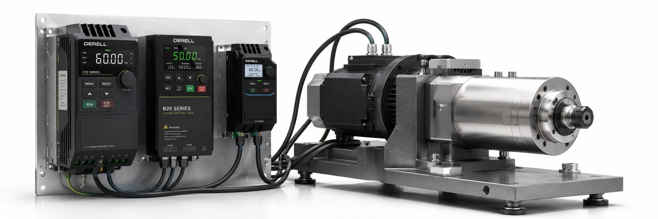
What Is a Spindle? How Do Spindle Motors and Drives Work?
A spindle is a precision shaft assembly that rotates a cutting tool or workpiece in a controlled manner. In milling, CNC routing, drilling and grinding, it usually rotates the tool; on a lathe, the main spindle normally rotates the workpiece. Although spindle motors and drives are often discussed together, the mechanical spindle, motor and drive perform different jobs.
Is a spindle simply a rotating motor?
A spindle assembly includes a shaft, precision bearings, housing and a tool or workpiece holding arrangement. Depending on the application, it may also incorporate lubrication, sealing, cooling and temperature monitoring. Collets, tapered tool holders and automatic tool changing mechanisms serve different requirements. An ER collet and an HSK tool interface are not directly interchangeable; the holding arrangement must suit the machine design.
A separate electric motor can drive the spindle through a belt, coupling or gear mechanism. In an integrated motor spindle, the motor and shaft form a single unit. Motor spindles may use induction or synchronous motors; compatibility with a particular drive should never be assumed from the word spindle alone.
Spindle speed, power and torque belong together
Shaft speed is expressed in RPM, or revolutions per minute. The appropriate speed depends on tool diameter, the tool manufacturer's cutting data, workpiece material and the operation. Small tools may need high speeds, whereas larger tools can require adequate torque at lower speeds. A higher maximum speed does not automatically improve machining in every material.
For mechanical shaft output, the approximate relationship is T (N·m) = 9550 × P (kW) / n (rpm). For example, 2.2 kW of mechanical output at 24,000 rpm corresponds to approximately 0.88 N·m. This calculation does not establish that the same power remains available at lower speeds. Use the manufacturer's speed–torque curve, duty rating and cooling conditions to determine the usable operating range.
What matters when choosing a spindle drive?
Electric spindle systems commonly use a variable frequency drive, or VFD, or a dedicated spindle drive suitable for the motor type. The kW rating alone is insufficient: check motor type, rated voltage, rated current, rated frequency, maximum speed and control method. The drive must support the required output frequency in the control mode that will actually be used.
200 Hz, 400 Hz and higher frequency values are not universal spindle settings. Use the motor nameplate voltage–frequency data and the manufacturer's parameters. Configure the V/F curve, minimum and maximum speed limits, and acceleration and deceleration times accordingly. A frequency reference from the CNC is a speed command; it does not mean that actual spindle speed is being measured.
Encoder feedback and machining accuracy
In suitable systems, encoder feedback supports actual speed measurement, closed-loop speed control and spindle orientation. It can also support synchronized machining or C-axis functions when the CNC and drive provide the necessary capabilities. However, fitting an encoder alone does not provide these functions; the drive interface, feedback resolution and control software must also be compatible.
Radial runout, bearing condition, tool holder cleanliness, balance and rigidity directly affect machining results. A damaged collet or an incorrectly seated tool can cause vibration and poor surface finish even when the spindle itself is sound. Assess runout using the specified measurement location, tool holder and manufacturer tolerance; there is no single acceptance limit for every spindle.
Cooling, maintenance and system compatibility
Spindle designs may use air or liquid cooling. Cooling the spindle housing and supplying cutting fluid to the machining zone serve different purposes. Coolant flow, temperature and lubrication conditions must follow the manufacturer's instructions. Check the adequacy of air cooling at low speeds, any required warm-up cycle and continuous operating limits for the particular model.
When selecting a spindle motor, consider the machining task, tool interface, speed–torque range, mounting and cooling together. When selecting a spindle drive, verify electrical compatibility and the CNC connections needed to meet those mechanical requirements. Evaluate the motor and drive as parts of the complete machine.
Technical References
GMN — Spindle motors and performance characteristics
GMN — Spindle drive systems and feedback