
When selecting VFD for a spindle!
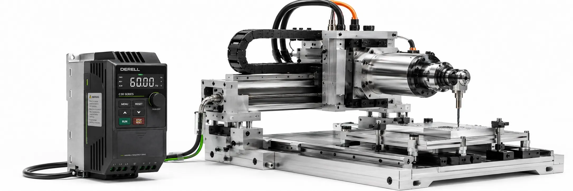
What Should You Check When Selecting a Spindle Drive?
Selecting a spindle motor drive requires more than matching the motor's kW rating. Assess the motor type, voltage, rated current, operating frequency, maximum speed, control method and speed–torque requirements together. An unsuitable combination can limit machining performance, cause motor overheating or drive trips, and exceed the system's operating limits.
Motor type and compatibility: Spindle applications may use induction motors or permanent-magnet synchronous motors. “High-speed spindle” does not, by itself, identify a separate electrical motor type. Check the motor designs, control algorithms and motor identification methods supported by the drive. See the spindle motor selection guide for mechanical and thermal considerations.
Supply and motor voltage: The drive's input phase configuration and supply voltage must suit the available electrical supply. Its output voltage capability must match the motor's connection arrangement and rated voltage. Do not assume that a standard 230 V-class drive can operate a motor requiring 400 V at the same rated conditions. Confirm single-phase input support or any special voltage-boosting capability in the product documentation.
Rated current and overload capability: Compare the motor nameplate current independently of the kW rating. The drive's continuous output current must meet the motor's requirements after applying any derating for ambient temperature, altitude and switching frequency. Check the overload percentage, permitted duration and repetition interval as well. A high short-term overload rating cannot compensate for insufficient continuous current capacity.
Maximum output frequency: Compare the motor's rated and maximum permitted electrical frequencies with the drive's limits. A standard VFD may not support a spindle requiring 400 Hz, 600 Hz or higher. Furthermore, the same drive can have different maximum frequencies in V/F and vector control modes. Use the limit applicable to the intended motor type, control mode and firmware version, rather than the highest number in the catalogue. Electrical frequency relates to mechanical speed through the motor's pole count and type.
Output frequency versus PWM frequency: The motor's electrical operating frequency is different from the power semiconductors' switching frequency. A PWM specification expressed in kHz does not mean that the motor can operate at that electrical frequency. Switching frequency can affect the motor current waveform, acoustic noise, drive losses and available output current. Configure it according to the motor and drive manufacturers' requirements for high-speed operation.
Speed and torque control: V/F control may be sufficient where it suits the application. Sensorless vector or encoder-based vector control may be appropriate when tighter speed regulation or a stronger response to load changes is needed. However, vector control is not automatically the best option for every high-speed spindle. Check the motor's electrical characteristics, operating frequency and supported speed range together. The drive cannot provide continuous torque beyond the motor's mechanical and thermal limits.
Open-loop or closed-loop operation: Without an encoder, a drive may estimate motor speed from electrical measurements and a motor model; this is different from measuring shaft speed directly. Systems using encoder feedback use information from actual rotation. For spindle orientation, precise synchronization, C-axis operation or rigid tapping, the drive, CNC controller and mechanical arrangement must support the required functions together. An encoder connection alone is insufficient.
Acceleration and braking: Set acceleration time according to total inertia, load and available motor torque. During deceleration from high speed, returned energy can raise the DC-link voltage. Short stopping times may require a suitable braking chopper and braking resistor, an external braking unit or a regenerative solution. Evaluate braking energy, cycle frequency, resistance and power capacity together. Do not select a resistance below the drive manufacturer's permitted minimum.
DC braking is a different method: DC injection braking dissipates energy as heat inside the motor; it is not a direct substitute for braking through a chopper and resistor. It may not suit every motor type or operating condition. Limit current and application time according to the motor's thermal limits and the drive instructions. The presence of a DC braking function alone does not establish suitability for a spindle with frequent stops or high inertia.
Protection and temperature monitoring: Review the scope of protection against overcurrent, overvoltage, undervoltage, drive overheating, motor overload and short circuits. If the motor has a PTC, Pt100, Pt1000 or another temperature sensor, the drive needs a suitable input or compatible interface; these sensor types are not directly interchangeable. An electronic thermal model does not necessarily measure actual motor temperature. Cabinet ventilation, ambient temperature and enclosure protection also affect selection.
Control inputs and communication: Decide whether the speed reference will come from the keypad, 0–10 V, 4–20 mA, digital preset-speed selection or a communication link. Match run, stop, ready and fault signals with the CNC controller or PLC. RS-485 is a physical interface; Modbus RTU is a protocol that can use it. An RS-485 connection alone does not establish protocol compatibility; verify the supported commands and register map.
Encoder support: Check the feedback signal type, supply voltage, resolution and maximum input frequency against the drive specifications. Some models provide a direct input, while others require a PG or encoder option card. At high speed, the encoder pulse frequency can exceed the card's input limit. Evaluate the roles of a motor encoder and a spindle-shaft encoder separately, particularly in belt-driven systems.
Motor cable and EMC: Follow the manufacturer's requirements for motor cable length, shielding, capacitance and protective earthing. The routing of power cables and sensitive control wiring also matters. An output reactor, dV/dt filter or another filter may be needed, but verify its permitted motor frequency, switching frequency, voltage and current. A standard output filter may be unsuitable for a 400–600 Hz spindle application. An input EMC filter and a motor-side output filter serve different purposes.
User interface and parameter configuration: Motor ratings, control mode, minimum and maximum frequency, ramps and input/output assignments should be clearly configurable. Parameter backup, fault history and monitoring displays simplify maintenance. Perform motor identification or autotuning using a method approved for the spindle by the manufacturer; some procedures can rotate the motor. Settings are not validated simply because they were copied from another machine.
Manufacturer and technical support: Obtain the hardware manual, parameter manual, motor compatibility information and option-card documentation for the exact model. In high-speed applications, assess the firmware, motor and intended control mode together. Brand recognition does not replace documented compatibility. Access to spare parts and application support also belongs in the purchasing decision.
Budget and total cost: When comparing spindle drive prices, consider more than the drive itself. Encoder cards, braking components, filters, cabling, cabinet cooling, commissioning, energy losses, maintenance and downtime affect total cost. An economical choice meets the required current, frequency and control performance under actual operating conditions, with the necessary accessories included in the assessment.
Related Topics and Product Categories
+ Spindle Motors and Drives Main Page
+ Variable Frequency Drives Main Page
+ What Are a Spindle Motor and Spindle Drive?
+ What to Check When Selecting a Spindle Motor
+ Spindle Motor and Drive Prices
+ Spindle Accessories and Technical Information
+ DERELL PLCs and Smart Relays
+ Used Spindle Motors and Drives
Technical References
GMN — Spindle drive systems, control modes and feedback
ABB DriveSize — Motor and drive dimensioning
Danfoss — Braking resistors, duty cycles and resistance selection
ABB FOCH du/dt Filter Manual — Output and switching frequency limits (PDF)
Numerical limits in these references apply to the products described. Use the specific documentation for the motor, drive, filter and braking equipment selected for your spindle application.