
what is spindle motor and drive?
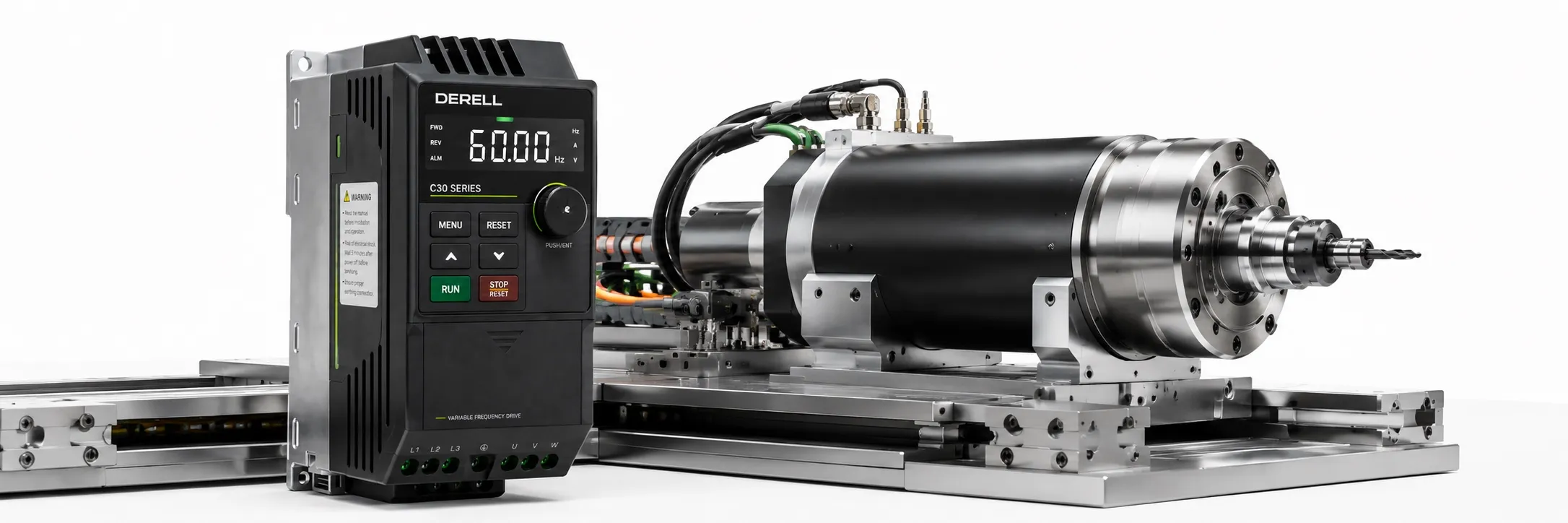
What Are a Spindle Motor and Spindle Drive?
A spindle motor rotates a cutting tool or workpiece at the required speed and torque in CNC machines, milling machines, lathes, grinders and similar machining systems. Spindle applications require more than an appropriate power rating: operating speed range, speed stability, low vibration, bearing arrangement and thermal behaviour also matter. High-speed models are common, but maximum speed is not the main priority in every spindle application.
The Difference Between a Spindle, Motor and Drive
The spindle is the precision rotating shaft assembly that carries the cutting tool, chuck or workpiece. Its mechanical components include the shaft, bearings, housing and holding arrangement. The spindle motor produces rotation, while the spindle drive manages the motor's electrical supply and control. The motor may be integrated into the spindle housing or drive the shaft through a belt, coupling or gears. Although these terms are often used together, they describe different parts of the system.
Spindle Speed, Power and Torque
Depending on the application, spindle systems can operate from a few thousand revolutions per minute to much higher speeds. Shaft speed is expressed in RPM. Small-diameter tools may require high rotational speeds to achieve the intended cutting speed. Larger tools and heavy cutting operations can instead require sufficient torque at lower speeds. Maximum speed and the kW rating alone do not establish machining capacity.
Assess the motor's rated speed, maximum speed, speed–torque curve, rated voltage, rated current, rated frequency and duty rating together. Motor spindles may use induction or synchronous motors. Air or liquid cooling, bearing design, tool interface and runout accuracy must also suit the application. Do not assume that the power specified at high speed remains available at low speed.
How Does a Spindle Inverter Work?
A spindle inverter, or spindle VFD, is an electronic drive that controls the motor's speed and operating behaviour. In a typical AC-supplied variable frequency drive, incoming power is first rectified and fed into a DC link. The inverter stage then produces an output with controlled frequency and voltage for the motor. The conversion path is AC input → rectifier → DC link → inverter → motor.
Most modern drives use pulse-width modulation, or PWM, to switch power semiconductors and supply the motor; the output voltage is not a pure mains-like sine wave. The relationship between electrical output frequency and shaft speed depends on the motor's pole count and type. Induction motors also exhibit slip, which changes with load. Consequently, a displayed frequency in Hz is not, by itself, a measurement of actual shaft speed.
How Does a CNC Controller or PLC Set Spindle Speed?
The speed or frequency reference may come from the drive keypad or supported interfaces such as 0–10 V, 4–20 mA, digitally selected preset speeds and communication networks. A PLC or CNC controller uses an appropriate supported interface. Run, stop, direction and speed commands can be managed through separate inputs or the same communication connection. Reverse operation must respect the limitations of the spindle and tool-holding arrangement.
Example: If an analog input is scaled as 0–10 V = 0–400 Hz, a 5 V signal requests a 200 Hz reference. This is only a scaling example, not a recommended setting for a particular motor. The reference is the requested value, not an actual speed measurement. Acceleration ramps, current limiting and motor load can cause the instantaneous shaft speed to differ from the command.
Can Every VFD Operate Every Spindle Motor?
No. Matching kW ratings do not establish motor–drive compatibility. The drive must support the motor type, rated voltage, rated current, required output frequency and load characteristics. For example, if the motor requires a 400 Hz output, the drive must provide it in the intended control mode. A drive's maximum frequency in V/F mode may differ from its limit in vector control.
Configure the V/F curve, motor nameplate parameters, minimum and maximum speed limits, and acceleration and deceleration times using the manufacturer's data. Account for any current derating associated with ambient temperature and switching frequency. Copying another spindle's parameters without checking them is not a sound commissioning method.
Control, Protection and Braking Functions
Depending on the model, the drive may provide vector control, current limiting, acceleration and deceleration ramps, overcurrent and overvoltage protection, motor thermal monitoring and fault diagnostics. Correct matching and configuration support controlled acceleration and more stable operation as the load changes. However, electrical protection functions cannot detect every bearing, tool holder, balance or cooling problem.
When a high-speed spindle decelerates, energy from the rotating assembly can flow back into the drive's DC link. An excessively short deceleration time can cause an overvoltage fault. The application may require a longer ramp, a suitable braking chopper and resistor, or a regenerative solution. Select braking equipment and stopping times within the limits of the drive and mechanical system.
What Does Encoder Feedback Do?
An encoder provides rotational feedback that a suitable system can use to monitor actual speed and angular position. Closed-loop speed control, spindle orientation, tool changing and synchronized machining can use this information. Whether the encoder measures the motor or the spindle shaft directly matters, particularly in belt-driven systems. An encoder alone does not provide C-axis operation or rigid tapping; the CNC controller, drive, feedback interface and mechanical arrangement must support the function together.
Why Do Cooling and Mechanical Condition Matter?
Motor heat, bearing temperature and thermal shaft expansion can affect machining accuracy. Air or liquid cooling must maintain the manufacturer's specified operating conditions. Cooling the spindle housing serves a different purpose from supplying cutting fluid to the machining zone. Bearing condition, radial runout, balance, tool holder cleanliness and mounting rigidity also affect surface finish; drive settings cannot resolve these mechanical problems on their own.
Evaluate the motor, inverter, spindle assembly, bearings, cooling and any encoder as a complete system. When selecting a spindle motor, establish the cutting tool, workpiece material and machining speed, then compare these requirements with the motor's available torque and the drive's capabilities. Correct selection and configuration support stable speed control and operation across different machining conditions.
Related Topics and Product Categories
+ Spindle Motors and Drives Main Page
+ Variable Frequency Drives Main Page
+ Spindle Accessories and Technical Information
+ What to Check When Selecting a Spindle Motor
+ What to Check When Selecting a Spindle Drive
+ Spindle Motor and Drive Prices
+ DERELL PLCs and Smart Relays
+ Used Spindle Motors and Drives
Technical References
ABB — How a variable speed drive works
GMN — Spindle motor types, power and torque characteristics
GMN — Spindle drive systems and encoder-based control
GMN — Motor and bearing cooling
Frequency, speed and cooling values on manufacturer pages apply to the products described. Use the technical documentation for the exact motor and drive models in your application.