
Simatic S5 Power Supply
Siemens SIMATIC S5 Power Supplies
Siemens SIMATIC S5 power supplies include rack supplies for CPU and backplane electronics, together with 24 V supplies used in suitable systems. This section covers the PS 930, PS 931, PS 950, PS 951 and PS 955 families across different S5 controller configurations.
Compare the complete order number, AC/DC input, output voltage and current, rack compatibility, cooling and backup battery arrangement. Internal controller power and field power for sensors, valves and contactors have different duties. Similar front panels or the same 955 designation do not establish interchangeability.
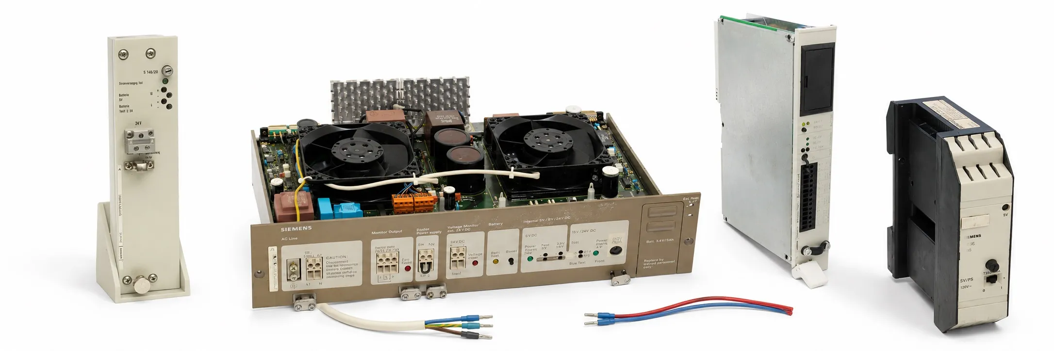
PS 951: the 3 A group for S5-115U
6ES5 951-7LB12, 6ES5 951-7LB13, 6ES5 951-7LB14 and 6ES5 951-7LB21 are AC-input PS 951 options; 6ES5 951-7NB12, 6ES5 951-7NB13 and 6ES5 951-7NB21 are DC-input PS 951 options. Siemens specifies 120/230 V AC input and 5 V DC / 3 A output for 6ES5 951-7LB21, and 24 V DC input and 5 V DC / 3 A output for 6ES5 951-7NB21. Check input ranges and hardware requirements for older suffixes against their own labels.
Include the internal power consumption of all installed modules and required monitoring signals when selecting a 3 A supply. Check the power supply and hardware revision required by each CP or IP module in its own documentation.
PS 951: higher-current versions and cooling
6ES5 951-7LD11, 6ES5 951-7LD12 and 6ES5 951-7LD21 are AC-input versions; 6ES5 951-7ND12, 6ES5 951-7ND21, 6ES5 951-7ND31, 6ES5 951-7ND32, 6ES5 951-7ND41 and 6ES5 951-7ND51 belong to the higher-current DC-input group. The complete suffix matters for isolation, battery arrangements and host-system approval.
For example, 6ES5 951-7ND51 has 24 V DC input and 5 V output. Its Siemens technical table specifies 7 A without a fan and 15 A with a fan. The 7/15 A rating therefore does not mean that every installation permits continuous operation at 15 A.
S5-115F: approved supplies and isolation
The S5-115F manual addresses 6ES5 951-7ND21, 6ES5 951-7ND31 and 6ES5 951-7ND41 under different conditions. 7ND21 has no galvanic isolation and requires additional external voltage monitoring; 7ND31 and 7ND41 are isolated. Because S5-115F operates without fans, its 5 V load must not exceed 7 A. Do not extend this approval to every PS 951 or every S5-115H arrangement.
PS 955: AC-input rack supplies
6ES5 955-3LC12, 6ES5 955-3LC13, 6ES5 955-3LC14, 6ES5 955-3LC41 and 6ES5 955-3LC42 belong to the PS 955 3LC group. 6ES5 955-3LF11, 6ES5 955-3LF12, 6ES5 955-3LF41, 6ES5 955-3LF42 and 6ES5 955-3LF44 belong to the 3LF group. Select the rack and output capacity by complete order number.
The S5-135U/155U manual specifies 120/230 V AC input and an 18 A main output in the 5 V class for 6ES5 955-3LC42, and 120/230 V AC input and 40 A in the 5 V class for 6ES5 955-3LF42. The 6ES5 955-3LF44 datasheet also specifies 230/120 V AC, 5 V / 40 A. Compare auxiliary outputs, fans and permitted rack combinations separately.
PS 955: 24 V DC-input options
6ES5 955-3NA11 and 6ES5 955-3NA12 form the 3NA group; 6ES5 955-3NC12, 6ES5 955-3NC13, 6ES5 955-3NC41 and 6ES5 955-3NC42 the 3NC group; and 6ES5 955-3NF11, 6ES5 955-3NF41 and 6ES5 955-3NF42 the 3NF group. A common 24 V input does not establish identical output currents or rack connections.
Siemens specifies 24 V DC input and 5 V / 10 A output for 6ES5 955-3NA12. 6ES5 955-3NC42 has an 18 A main output and 6ES5 955-3NF42 a 40 A main output. For these last two models, the technical tables specify 5.1 V DC as the rated main output; distinguish the 5 V product class from the exact table value.
PS 955 7NC supplies for S5-155H
6ES5 955-7NC11 is a CC/ZG 155H central-rack supply with 24 V DC input and a 14 A main output in the 5 V class. 6ES5 955-7NC12 is a separate order number examined under the same 155H heading. Do not assume interchangeability between 7NC and 3NC/3NF supplies simply because they share the 955 family name.
PS 950: older rack supplies and the 24 V supply
6ES5 950-1AB61 is a 24 V DC-input, 5 V / 8 A supply for the 182-3K expansion unit. 6ES5 950-3AA51 belongs to the older PS 950 rack-supply range; compare its exact label with the intended central or expansion unit.
6ES5 950-8MD11 converts 115/230 V AC to 24 V DC. The Siemens table permits up to 10 A at 50 °C in a horizontal arrangement and up to 8 A at 60 °C in a vertical arrangement. Its 24 V output serves a different purpose from a 5 V backplane supply.
PS 930 and PS 931 for S5-100U
6ES5 930-8MD11 is the PS 930 with 115/230 V AC input and 24 V DC / 1 A output; 6ES5 931-8MD11 is the PS 931 with 115/230 V AC input and 24 V DC / 2 A output. Because of the PS 930 no-load output characteristic, Siemens limits it to powering S5-100U CPUs. It should not be selected as a general-purpose 24 V field supply.
S5-110A supplies and the S5-110S housing
6ES5 930-7AA11 and 6ES5 930-7AA12 have 220 V AC input; 6ES5 930-7AA21 has 115 V AC input; 6ES5 930-7AA31 has 24 V DC input. These S5-110A supplies serve the internal 5 V circuit. Check differences such as the 7AA12 built-in mains filter together with the wiring arrangement.
6ES5 932-3SA11 is assessed as an S5-110S 932 housing with power supply. Confirm separately whether the CPU and other boards are included. An output-current rating documented for 932-3SA12 must not be transferred directly to 3SA11.
CPU and central-unit codes listed in this category
6ES5 100-8MA01 and 6ES5 100-8MA02 are CPU 100 models; 6ES5 102-8MA01 and 6ES5 102-8MA02 are CPU 102 models; 6ES5 103-8MA01 and 6ES5 103-8MA02 are CPU 103 models. They are S5-100U central processing units. Their internal power conversion does not make them independent cabinet power supplies.
6ES5 130-3WE63 belongs to the S5-130W central-unit group. Record the complete assembly code separately from the power supply, CPU and installed boards. Confirm delivery contents rather than inferring them from the category name or example image.
ET 200C power supply connector: 762-2CS11
6ES5 762-2CS11 combines an external power supply and SINEC L2-DP bus into a common outgoing cable. It is an ET 200C power supply connector, not an AC-to-24 V converter. The Siemens manual specifies a maximum incoming current of 4 A; the connector has no bus station address of its own.
Replacement checks and used-equipment testing
Record the rack code, terminal arrangement, output-current budget, fans, battery monitoring and jumper positions. Do not assume that a supply is assigned an I/O address. Trace any monitoring signals and their relationship with the CPU and interface modules through the system diagram.
Provide the complete model, quantity, working/faulty condition, nameplate photographs and price for used-equipment assessment. An unloaded voltage reading differs from operation under load in a suitable rack. Identify the load, orientation, temperature, fans and tested outputs in the test record.
Editor’s note
Compare the complete rack and power supply labels first. A reference to “a 951” is insufficient for replacement. Establish the AC/DC input, suffix and terminal arrangement before applying power, including any voltage-selector position.
For intermittent shutdowns, check the incoming supply, loose terminals and output during load changes together. Fan noise, obstructed airflow and faults appearing after warm-up may be missed by an unloaded voltage check.
Read the 7/15 A rating together with its cooling conditions. Do not budget for 15 A in S5-115F. A higher-current supply does not resolve an incompatible rack, isolation arrangement or connection.
Before removal, record the program backup, battery condition and monitoring settings. Older “without battery” descriptions may refer to delivery contents. Battery support and inclusion of a battery in the supplied item are separate questions.
Inspect fans, battery leakage/corrosion, connectors and signs of overheating. Do not turn an adjustment potentiometer at random because the output appears low. Use the measurement point and permitted value documented for that exact supply.
Agree which outputs were tested, the applied load and the included parts in writing. Workshop testing is possible, with scope determined by the available hardware. All sales require an invoice; returns are not accepted. To offer S5 equipment for sale, send the model, quantity, condition, nameplate photographs and asking price to otomasyonavm@gmail.com.
OtomasyonAVM resources and PDFs
For system selection, see About Siemens S5 PLCs, the SIMATIC S5 main page and S5 central and expansion units. Start with the S5 system manuals and PDF files archive for wiring and technical tables; match the complete model and document edition.
Related topics
Review S5 racks and mounting frames, S5 cables and connectors, S5 memory cards, S5 interface modules, S5 communication modules, S5 positioning modules and S5 special modules when assessing the supply load and system compatibility.
Browse SIMATIC S5
+ SIMATIC S5 | Siemens S5 PLCs | S5 module groups | S5 CPU models | Used Siemens equipment | All used equipment
Siemens and external references
+ S5-115U Programmable Controller Manual — EWA 4NEB 811 6130-02b; chapter 15.2.2; English.
+ S5-115F Programmable Controller Manual — EWA 4NEB 811 6148-02; table 3-3; English.
+ S5-135U/155U System Manual — C79000-G8576-C199-07; chapters 4.3–4.4; English.
+ S5-155H CPU 948R/948RL Manual — Volume 1 — 6ES5 998-4SR21; Part IV/3; English.
+ S5-100U System Manual — CPU 100/102/103 — EWA 4NEB 812 6120-02b; chapter 14; English.
+ S5-100U CPU 100/102/103 — PS 950 — GWA 4NEB 812 6011-09b; pages 2-14–2-16; Russian.
+ ET 200C Manual — Power Supply Connector — EWA 4NEB 812 6119-01b; chapter 3.9; German.
+ S5-110A Programmable Controller — Operating Instructions — Siemens; power supply and connection sections; English.
+ SIMATIC S5 Catalog ST 53 — Siemens ST 53, 1985; German.
+ 6ES5 955-3LF44 — Siemens Data Sheet — Siemens; 28 April 2018; English.