
Overvoltage Protection Fuses
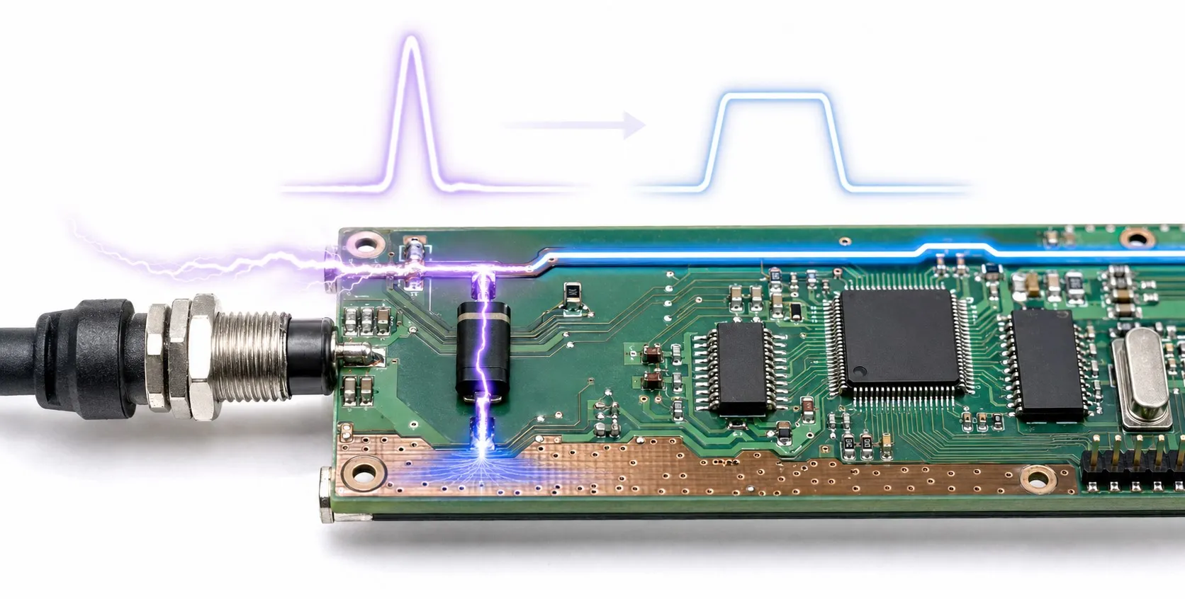
Limiting voltage surges and interrupting fault current
Hello, overvoltage protection and overcurrent protection perform complementary jobs. A product described as an “overvoltage protection fuse” may actually be a surge protective device (SPD), a protected module, or a circuit used with a fuse. However, MOVs, GDTs and TVS diodes are not types of conventional fusible-link fuse. When comparing fuse technologies or deciding which type of fuse to choose, first identify the fault you need to protect against.
Editor’s note: A 250 V marking on a fuse does not mean it opens when the voltage reaches 250 V. It identifies its rated voltage under specified conditions. The primary function of a fuse is to interrupt overcurrent. An SPD’s maximum continuous operating voltage and voltage protection level are separate ratings.
Transient surges, sustained overvoltage and overcurrent
Transient overvoltage is a short voltage disturbance associated with events such as lightning or switching. An SPD provides a suitable path for surge current and limits the voltage across its terminals. Depending on the protection arrangement, current is diverted between line and neutral or between live conductors and earth; not every protective component requires an earth connection.
Sustained or longer-duration overvoltage requires a different approach. For example, loss of neutral in a three-phase installation can disturb the voltages supplied to single-phase loads. An SPD is not a regulator that continuously restores excessive supply voltage to normal. The application may require voltage monitoring and a suitable disconnection arrangement. Understanding the differences between protective devices directly affects this choice.
Overloads and short circuits are addressed by fuses or suitable circuit breakers. The fuse current rating must be considered alongside load current; high-power equipment also requires attention to starting current and protection coordination. Installing one protective device does not automatically provide every other protection function.
What do MOVs, GDTs and TVS diodes do?
Metal oxide varistor (MOV): A varistor is a nonlinear, voltage-dependent component. Its conductivity increases during a surge, limiting voltage. Repeated surges and overstress can change its characteristics. It is not a one-time fuse replaced after every surge; its service life depends on the stresses it experiences.
Gas discharge tube (GDT): Ionization of its gas creates a low-impedance conducting path. Extinguishing conduction after the surge is important. Particularly in power circuits, follow current must be considered; an arbitrarily selected GDT should not be connected directly across the mains.
Transient voltage suppressor (TVS) diode: This component limits voltage on electronic supplies and signal lines. VRWM is the reverse working voltage, VBR is the breakdown voltage, and VC is the clamping voltage at a specified pulse current. Treating these as the same value can leave a sensitive input inadequately protected.
Combined solutions: A module may contain MOVs, GDTs, a thermal disconnector and a fuse. A thermal disconnector can isolate an overheating protection branch; it should not be assumed capable of interrupting every short circuit. A fused SPD combines distinct protection functions in one assembly.
Choosing Type 1, Type 2 and Type 3 protection
Type 1 protection is used where partial lightning current may enter the installation and is characterized by a 10/350 µs impulse current. Type 2 is commonly used for surge protection in distribution boards and is assessed using an 8/20 µs current impulse. Type 3 provides supplementary protection near sensitive equipment. Combined Type 1+2 products are also available. Stage locations and compatibility must follow the manufacturer’s coordination information.
Reading the ratings correctly
Uc is the maximum voltage that can be continuously applied to the SPD; Up is its voltage protection level under specified tests. Compare Up with the equipment’s impulse withstand capability. AC/DC operation, the TT, TN or IT earthing system and the connection arrangement affect selection. Choosing the lowest voltage printed on a device is not a reliable selection method.
In is nominal discharge current, Imax is maximum discharge current, and Iimp is lightning impulse current. These are not continuous load-current ratings. Values specified for 8/20 µs and 10/350 µs waveforms are not directly equivalent. Neither a joule rating nor response time alone is sufficient; waveform and manufacturer test conditions must also be considered.
Why use a fuse with an SPD?
If an SPD reaches end of life and develops a low-impedance fault, current can flow from the supply into that fault. A backup fuse or suitable circuit breaker is used to interrupt this fault current safely. Selection must follow the SPD manufacturer’s specified device type, maximum rating and coordination table. Existing upstream protection may already meet the requirements, so a separate fuse is not always necessary. There is no universal fuse current rating for every SPD.
Fuse selection considers rated voltage, AC/DC suitability, breaking capacity, the time-current curve and, where relevant, I²t. Breaking capacity must not be lower than the prospective short-circuit current at the installation point. Compliance with fuse standards alone does not prove coordination with a particular SPD. If a fuse repeatedly blows, increasing its current rating without investigating the fault is not a solution.
Two practical examples
A 230 V control panel: The input fuse of a 24 V power supply and the panel’s surge protection serve different purposes. Select the SPD for the supply, earthing arrangement, lightning exposure and power supply impulse withstand capability. Keep connections short and direct: additional voltage along long conductors worsens the protection seen by the load. Keeping the combined connection length at approximately 0.5 m or less is a basic design target for the appropriate connection arrangement; follow the product instructions for details.
A 24 V electronic input: Consider an illustrative circuit operating at 24 V, reaching 28 V during normal operation, with a 36 V absolute maximum input limit. The TVS VRWM must accommodate the normal upper voltage. Its VC at the relevant surge current, including additional connection voltage, must remain below the input limit. A “24 V TVS” label is not enough. Allow for tolerances and design margin. If the required window cannot be achieved, an additional stage or active protection is needed. This example explains the selection process; it is not a component recommendation.
Inspection, replacement and protection limits
During panel layout and maintenance checks, inspect the SPD status indicator, any alarm contact, connections and backup protection. Some designs continue supplying the load after the protection module disconnects. Equipment still running does not prove that surge protection remains operational. Do not assume that a line fuse will always open in time to prevent MOV overheating.
The criteria for replacing a fuse differ from those for replacing an SPD cartridge. Work must follow safe isolation and replacement precautions, and replacement modules must match the manufacturer’s instructions. For electrical safety at home, fuses, residual-current devices and SPDs also perform different jobs. An SPD cannot eliminate every fault, power interruption or lightning effect of any magnitude.
Related topics
Fuse and protection options: Compare current fuses, thermal fuses, electronic fuses, DC fuses and fast-acting and time-delay fuses to understand different fault conditions and operating characteristics.
Complementary topics: Explore supply withstand capability in power supplies, sensitive inputs in PLC systems, communication-port protection on RS-485 networks, surge-current return paths and earthing, and noise attenuation with EMC filters. Unless a surge protection function is specifically provided, an EMC filter should not be treated as a replacement for an SPD.
Technical sources
Eaton — Yıldırım ve Aşırı Gerilim Koruması
Bourns — Designing Effective Surge Protection for AC and DC Powered Systems
Texas Instruments — How to Select a Surge Diode
Littelfuse — Integrated Overcurrent/Overvoltage/Overtemperature Solutions for Industrial Equipment
Schneider Electric — The Surge Protection Device (SPD)
Schneider Electric — Common Characteristics of SPDs According to the Installation Characteristics
Schneider Electric — Selection of External Short Circuit Protection Device (SCPD)