
Invt VFD Modbus adress
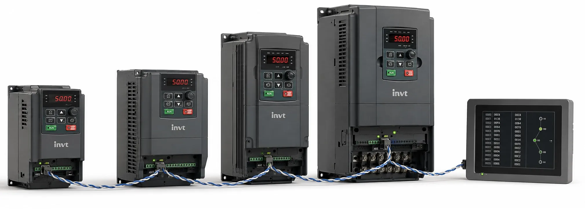
INVT VFD Modbus RS485 Addresses
This page lists commonly used Modbus addresses for INVT variable frequency drives, including run commands, frequency reference, drive status and parameter registers.
Many INVT Goodrive models use the same basic Modbus RS485 register structure. However, the available parameter groups and monitoring functions can vary by drive model and firmware version. Always compare the addresses with the manual for the specific VFD being commissioned.
Model-specific documents are available in the INVT user manuals section.
Address Format Used on This Page
HEX: INVT Modbus register address
DEC: 400001-based Holding Register notation used on this page
Important: Some PLC, HMI and SCADA systems expect the raw register offset rather than a 4xxxxx Holding Register number. Check the addressing convention used by your software before entering these values.
2000H - Drive Control Command
HEX: 2000H
DEC: 408193
Access: Read / Write
Command values written to 2000H:
1: Run forward
2: Run reverse
3: Forward JOG
4: Reverse JOG
5: Stop
7: Fault reset
2001H - Frequency / Speed Reference
HEX: 2001H
DEC: 408194
Access: Read / Write
This is one of the most frequently used INVT Modbus registers. It is used to send the frequency reference to the drive when the frequency command source is configured for communication control.
2100H - Drive Operating Status
HEX: 2100H
DEC: 408449
Access: Read Only
Typical status values:
1: Running forward
2: Running reverse
3: Stopped
4: VFD fault
Note: These values represent operating states returned by the 2100H status register. Additional status values may exist on some INVT series.
3001H - Set Frequency
HEX: 3001H
DEC: 412290
Access: Read Only
This register can be used to read the active frequency reference being used by the drive. The reference may originate from an analog input, digital setting, PID control or another configured command source.
INVT Parameter Group Starting Addresses
The following addresses represent the first register in each INVT parameter group. Parameters that follow within the same group continue sequentially.
P00.00 - HEX: 0000H - DEC: 400001
P01.00 - HEX: 0100H - DEC: 400257
P02.00 - HEX: 0200H - DEC: 400513
P03.00 - HEX: 0300H - DEC: 400769
P04.00 - HEX: 0400H - DEC: 401025
P05.00 - HEX: 0500H - DEC: 401281
P06.00 - HEX: 0600H - DEC: 401537
P07.00 - HEX: 0700H - DEC: 401793
P08.00 - HEX: 0800H - DEC: 402049
P09.00 - HEX: 0900H - DEC: 402305
P10.00 - HEX: 0A00H - DEC: 402561
P11.00 - HEX: 0B00H - DEC: 402817
P12.00 - HEX: 0C00H - DEC: 403073
P13.00 - HEX: 0D00H - DEC: 403329
P14.00 - HEX: 0E00H - DEC: 403585
P15.00 - HEX: 0F00H - DEC: 403841
P16.00 - HEX: 1000H - DEC: 404097
For example, parameter P05.06 corresponds to register 0506H. Whether a particular parameter can be read or written should be checked in the parameter table for the relevant INVT model.
P17 Monitoring Parameters
P17.xx parameters are monitoring values and are read only. The exact number of available P17 parameters may vary between INVT drive families.
P17.00 - HEX: 1100H - DEC: 404353 - Current set frequency
P17.01 - HEX: 1101H - DEC: 404354 - Output frequency
P17.02 - HEX: 1102H - DEC: 404355 - Ramp reference frequency
P17.03 - HEX: 1103H - DEC: 404356 - Output voltage
P17.04 - HEX: 1104H - DEC: 404357 - Output current
P17.05 - HEX: 1105H - DEC: 404358 - Motor speed
P17.06 - HEX: 1106H - DEC: 404359 - Torque current
P17.07 - HEX: 1107H - DEC: 404360 - Exciting / magnetizing current
P17.08 - HEX: 1108H - DEC: 404361 - Motor power
P17.09 - HEX: 1109H - DEC: 404362 - Output torque (%)
P17.10 - HEX: 110AH - DEC: 404363 - Estimated motor rotor frequency
P17.11 - HEX: 110BH - DEC: 404364 - DC bus voltage
P17.12 - HEX: 110CH - DEC: 404365 - Digital input-terminal status
P17.13 - HEX: 110DH - DEC: 404366 - Digital output-terminal status
P17.14 - HEX: 110EH - DEC: 404367 - Keypad digital adjustment value
P17.15 - HEX: 110FH - DEC: 404368 - Torque reference
P17.16 - HEX: 1110H - DEC: 404369 - Linear speed
P17.17 - HEX: 1111H - DEC: 404370 - Reserved
P17.18 - HEX: 1112H - DEC: 404371 - Counter value
P17.19 - HEX: 1113H - DEC: 404372 - AI1 analog input value
P17.20 - HEX: 1114H - DEC: 404373 - AI2 analog input value
P17.21 - HEX: 1115H - DEC: 404374 - AI3 analog input value
P17.22 - HEX: 1116H - DEC: 404375 - HDI input frequency
P17.23 - HEX: 1117H - DEC: 404376 - PID reference value
P17.24 - HEX: 1118H - DEC: 404377 - PID feedback value
P17.25 - HEX: 1119H - DEC: 404378 - Motor power factor
P17.26 - HEX: 111AH - DEC: 404379 - Current drive running time
P17.27 - HEX: 111BH - DEC: 404380 - Simple PLC / current multi-step speed stage
P17.28 - HEX: 111CH - DEC: 404381 - ASR controller output (%)
P17.29 - HEX: 111DH - DEC: 404382 - Reserved
P17.30 - HEX: 111EH - DEC: 404383 - Reserved
P17.31 - HEX: 111FH - DEC: 404384 - Reserved
P17.32 - HEX: 1120H - DEC: 404385 - Motor magnetic flux linkage
P17.33 - HEX: 1121H - DEC: 404386 - Exciting current reference
P17.34 - HEX: 1122H - DEC: 404387 - Torque current reference
P17.35 - HEX: 1123H - DEC: 404388 - AC input current
P17.36 - HEX: 1124H - DEC: 404389 - Output torque (Nm)
P17.37 - HEX: 1125H - DEC: 404390 - Motor overload counter
P17.38 - HEX: 1126H - DEC: 404391 - PID output (%)
P17.39 - HEX: 1127H - DEC: 404392 - Reserved
P17.40 - HEX: 1128H - DEC: 404393 - Process PID proportional gain
P17.41 - HEX: 1129H - DEC: 404394 - Process PID integral time
P17.42 - HEX: 112AH - DEC: 404395 - Process PID differential time
Note: Some monitoring functions in the P17 range may be model-dependent. Verify the P17 table in the manual for the exact INVT drive and firmware version used in the application.
Additional Parameter Group Starting Addresses
P18.00 - HEX: 1200H - DEC: 404609
P19.00 - HEX: 1300H - DEC: 404865
P20.00 - HEX: 1400H - DEC: 405121
P21.00 - HEX: 1500H - DEC: 405377
P22.00 - HEX: 1600H - DEC: 405633
Before Using Modbus Control
- Configure the VFD run-command source for communication control where required.
- If the frequency reference will be sent by Modbus, select the appropriate communication frequency-reference source.
- Make sure the PLC, HMI or SCADA uses the same slave address, baud rate, parity and stop-bit settings as the drive.
- Do not confuse the HEX register address with 4xxxxx Holding Register notation.
- Check whether a parameter is writable while the drive is running before attempting to change it.
- Verify model-specific monitoring registers before commissioning a new INVT series or firmware revision.
Related INVT Resources
+ INVT VFD Modbus Address Reference
+ INVT User Manuals and Technical Documents
+ INVT Commissioning and Application Notes