
IEC 60898
Choosing trip characteristics and breaking capacity for circuit protection
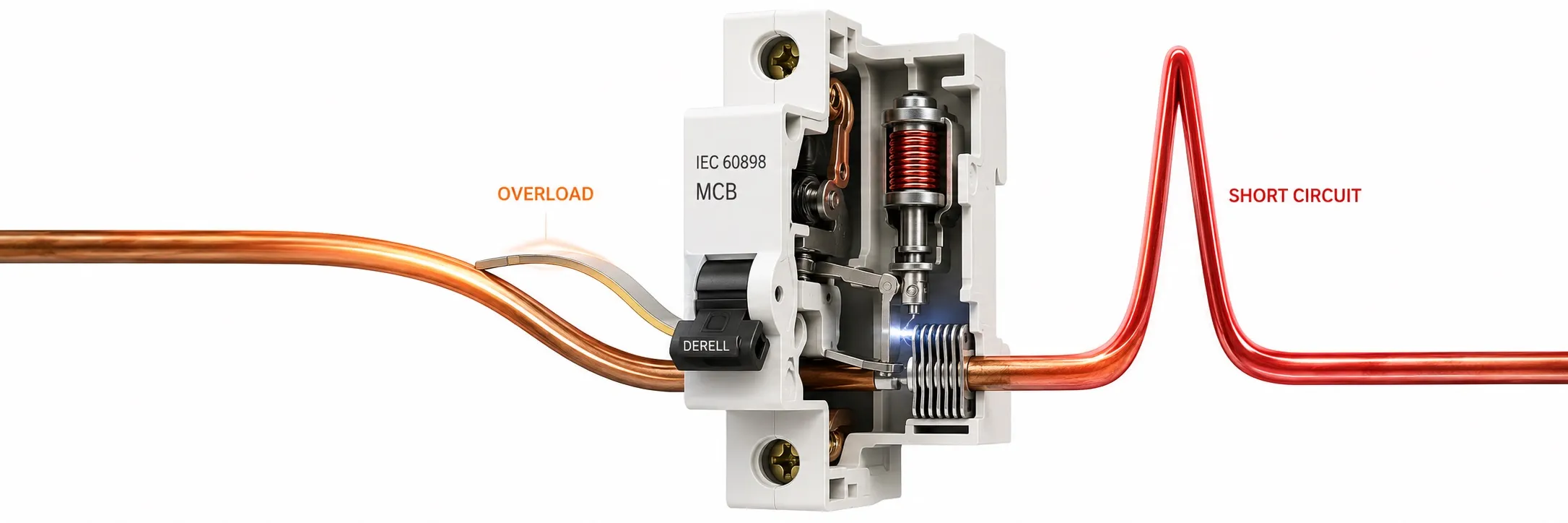
Hello, the IEC 60898 series covers overcurrent circuit-breakers for household and similar installations. Commonly called miniature circuit-breakers or MCBs, these devices disconnect overloaded or short-circuited circuits to help protect their conductors. The distinction between a fuse and a circuit-breaker matters: IEC 60898 is not the standard for fusible devices covered by IEC 60269.
AC and DC parts of the series
IEC 60898-1:2015+A1:2019 covers AC air-break circuit-breakers operating at 50 Hz, 60 Hz or 50/60 Hz, with rated voltage up to 440 V between phases, rated current up to 125 A and rated short-circuit capacity up to 25 kA. These are scope limits, rather than ratings available on every product.
IEC 60898-2:2016 adds requirements for single- and two-pole devices suitable for DC as well as AC operation. Its DC limits are 220 V for one pole and 440 V for two poles, 125 A and 10 kA. IEC 60898-3:2019+A1:2022 covers DC circuit-breakers, with limits of 440 V DC, 125 A and 10 kA. An AC rating does not authorize DC use; check the product's DC rating, pole arrangement and any polarity requirements separately.
Suitability for a workplace or machine panel depends on the application and product documentation, not simply the building's description. Circuit-breakers covered by IEC 60947-2 follow a different framework for installation and operation by instructed or skilled persons. A model carrying both standards may have different ratings under each.
What do B, C and D characteristics mean?
In a common thermal-magnetic MCB, the thermal release responds to the magnitude and duration of an overload, while the magnetic release provides rapid operation at high current. B, C and D trip curves primarily distinguish the instantaneous magnetic tripping region. The letter does not specify breaking capacity.
The instantaneous bands are 3–5 × In for B, 5–10 × In for C and 10–20 × In for D. B may suit loads with low inrush; C or D may be considered for higher starting currents. Selection must account for the load's current-time behaviour and the installation's disconnection requirements. “B for homes, D for industry” is not a sufficient selection rule.
For the same 16 A rated current, the bands are 48–80 A for B16, 80–160 A for C16 and 160–320 A for D16. These are tolerance bands, not single exact trip points. An overcurrent below the magnetic band can still cause thermal tripping, depending on its duration.
Editor's note: Replacing a repeatedly tripping B16 with a C16 or D16 does not establish that the fault has been resolved. A higher magnetic threshold can make rapid disconnection harder to achieve, particularly on long circuits. Increasing the current rating can also weaken cable overload protection. Assess the load, connections and measured conditions first.
Thermal tripping and enclosure temperature
IEC 60898-1 thermal tests use a 30 °C reference temperature, a 1.13 × In conventional non-tripping current and a 1.45 × In conventional tripping current. For a 16 A device, these are 18.08 A and 23.2 A, assessed over a conventional period of one hour under the specified test conditions. They are neither instantaneous thresholds nor permitted continuous load ratings.
Actual enclosure temperature, adjacent loaded devices and heat dissipation affect usable current. Follow the manufacturer's temperature and grouping correction tables. The current marked on the front should not be assumed to remain fully available inside a hot enclosure.
In and Icn describe different capabilities
In is the rated current under stated conditions; Icn is the rated short-circuit capacity within the IEC 60898 framework. For example, a device marked C16 and 6000 A has a 16 A rated current and a 6 kA short-circuit capacity at its specified voltage. The 6000 A marking is neither its load current nor its magnetic trip threshold.
Breaking capacity must suit the prospective short-circuit current at the installation point. If that value is calculated as 8 kA, a standalone 6 kA Icn rating is insufficient. Icu and Ics ratings in IEC 60947-2 documentation should not be treated as directly interchangeable with Icn: read the standard, voltage and test conditions together. Ics denotes rated service short-circuit breaking capacity.
Check cable protection and available fault current together
Basic overload coordination starts with Ib ≤ In ≤ Iz: Ib is the design load current, In the protective device's rated current and Iz the cable's current-carrying capacity under its actual installation conditions. Also assess I2 ≤ 1.45 × Iz, where I2 is the current ensuring operation within the conventional time. Cable cross-section and current-carrying capacity must account for installation method, temperature and grouping.
The device must interrupt high fault currents while also disconnecting promptly at the lower fault current available at a circuit's far end. This makes earth-fault loop impedance and protective earthing relevant to trip-curve selection. A high kA rating alone does not establish adequate protection.
MCB, RCCB and RCBO functions
MCBs, RCCBs and RCBOs perform different functions. An MCB provides overcurrent protection without inherently detecting residual current. An RCCB in the IEC 61008 family provides residual current protection without integral overcurrent protection. An RCBO in the IEC 61009 family combines residual current and overcurrent protection.
A B trip curve on an MCB is unrelated to the classification of a Type B residual current device. The first describes overcurrent tripping behaviour; the second concerns sensitivity to residual current waveforms. The two “B” designations are not interchangeable.
Selectivity, installation and assessment after a fault
Selectivity means the appropriate protective device nearest the fault operates while other circuits remain supplied. A difference in upstream and downstream current ratings alone does not guarantee it. Cascading or backup protection is a different coordination method that uses the upstream device's current limitation. Use manufacturer tables for the specific device combination, voltage and fault level.
Distribution-board layout should account for terminal-compatible conductors, specified tightening torque, busbar compatibility and heat dissipation. Check the model, pole arrangement, voltage, curve, In, breaking capacity under the relevant standard and traceability information against the documentation. A standard number on a product does not establish conformity of the complete installation.
When investigating why a circuit-breaker trips, first establish whether the MCB or residual current device operated. A device that trips immediately after resetting should not be repeatedly forced back on. After damage, overheating or a severe short circuit, follow manufacturer guidance and obtain a competent assessment before reuse. Replacement and connection work requires competent personnel, safe isolation and verification that the installation is de-energized.
Related technical pages
EN 60898
Circuit breakers, residual current protection and electrical safety
Guide to IEC standards
Sources
ABB: tripping characteristics of miniature circuit-breakers
Hager: MCB, RCCB and RCBO technical questions
Schneider Electric: thermal tripping tests and reference temperature
Schneider Electric: fundamental circuit-breaker ratings
Schneider Electric: conductor and protective-device coordination