
How do servo motors play a role in position control?
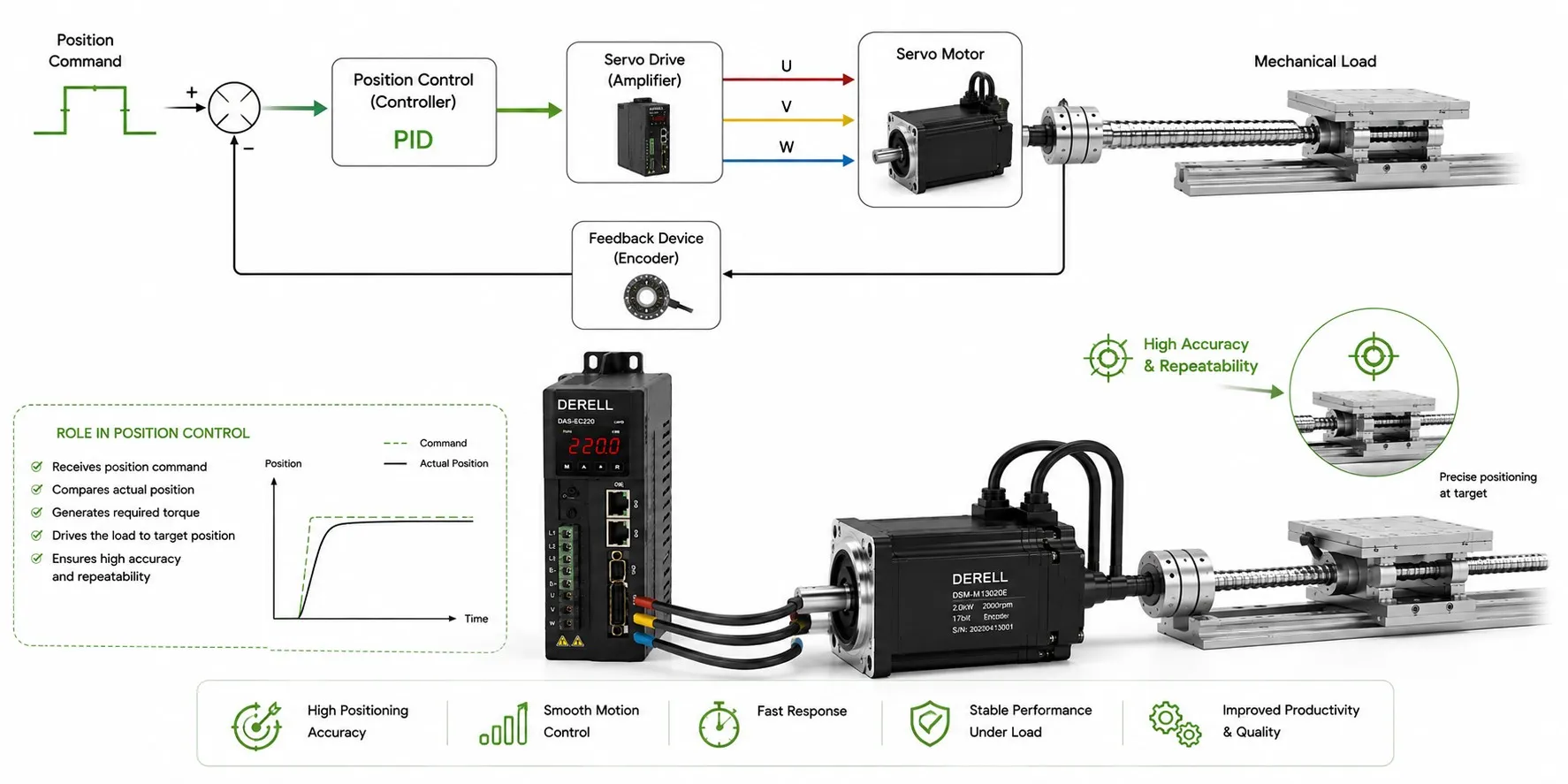
Turning a position command into controlled motion
In position control, a servo motor produces controlled torque to move a load to its target and, when required, hold it there. The servo system combines a controller that plans motion, a drive that supplies motor current and feedback that reports position. The motor performs the mechanical work; the calculation comparing commanded and measured position runs in the drive or a higher-level controller.
How are the responsibilities divided?
The axis controller defines the destination and trajectory. The servo drive regulates current to produce the torque requested by the control system. Feedback provides measured position and, depending on the architecture, velocity information. An encoder or resolver must match the drive interface and the measurement requirements.
A common arrangement uses an outer position loop to request velocity, a velocity loop to request torque/current, and an inner current loop to regulate motor current. These position, speed and torque controls work together. Their location and structure depend on the operating mode; a positioning application need not put every calculation in one device.
What happens when measured position differs from the target?
The basic comparison is e = commanded position − measured position. If the commanded position is currently 50.00 mm and feedback reads 49.80 mm in the same coordinate system, the difference is 0.20 mm. The controller uses this difference and the system dynamics to calculate a correction. The motor's speed and torque response moves or decelerates the load while feedback continues to update.
Reaching the target does not necessarily reduce motor current to zero. An enabled, powered control loop may generate balancing torque against a load that would otherwise displace the axis. Holding duty must remain within the motor's continuous-current and temperature limits, even when the shaft is stationary.
Converting shaft rotation into travel
Consider a directly coupled screw that advances 5 mm per revolution. Ideally, a 50 mm move requires 10 motor revolutions. With feedback evaluated as 10,000 effective counts per revolution, this corresponds to a change of 100,000 counts. The nominal measurement increment is 0.0005 mm, or 0.5 µm. That increment describes resolution, not the accuracy of the complete machine.
A gearbox, belt transmission or different screw lead changes the conversion. Correct transmission calculations and position scaling are essential. Electronic gearing can set the relationship between command units and motion; the physical transmission and screw lead still need to be included. Input command pulses and encoder feedback counts should not be assumed to represent the same quantity.
A coordinate reference is different from a move type
An absolute move goes to a target in the established coordinate system, such as X = 50 mm. A relative move adds a distance to the current position, such as +10 mm. These command types are separate from the distinction between absolute and incremental feedback.
Homing establishes the machine reference. An axis using incremental feedback may need a reference procedure at startup. Suitable absolute feedback and configuration can reduce or eliminate a startup homing move. The relationship to machine zero, the measuring range and the stored offset must still be verified.
Does shaft position always equal load position?
A motor-mounted encoder does not directly observe every clearance or deflection in the transmission. During reversal, the motor may rotate before the load moves by the corresponding amount. A linear encoder on the load can help measure the actual load position when the control architecture supports it. Assess position accuracy together with screw error, backlash, stiffness, temperature and measurement quality.
Getting a clean response at the destination
During drive configuration, verify scaling and feedback direction before using auto-tuning or appropriate manual settings. Excessive controller gains can cause oscillation around the target. Velocity and acceleration feedforward can reduce following error. Evaluate signal filters for the delay they introduce as well as the noise they remove.
Reaching the destination, settling inside an error band and tracking throughout the move are separate performance measures. Good dynamic performance requires velocity, acceleration and jerk limits that suit the mechanics. Interpolation defines the path between endpoints, rather than only the final destination.
What does this enable on a production machine?
Typical tasks include placing a cutting tool at a programmed coordinate, advancing packaging material by a defined distance and moving robot joints to commanded angles. In coordinated multi-axis motion, the individual axes must follow their commands while preserving the shared path and timing. A network such as EtherCAT carries commands and feedback; mechanical accuracy still depends on the complete system.