
IEC 60947-6-2
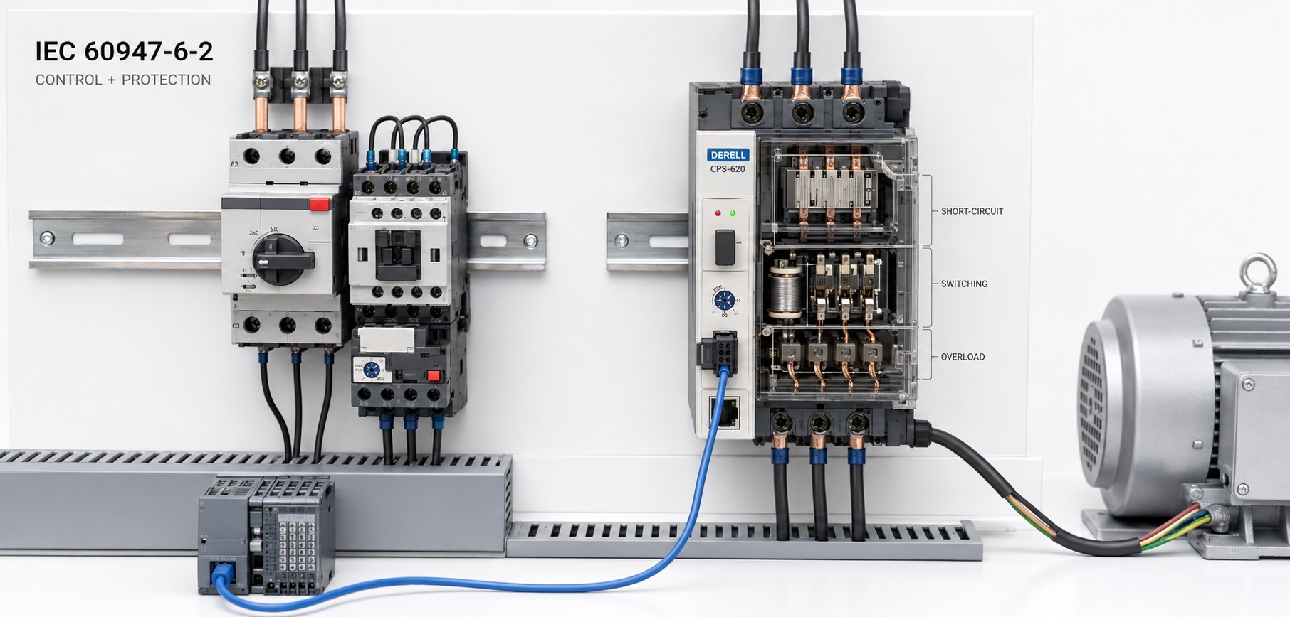
Considering motor control and protection together
IEC 60947-6-2 addresses CPS equipment that combines control and protective functions for circuits and motors. CPS stands for Control and Protective Switching Devices. Starting, stopping and overcurrent protection of an AC motor are considered as coordinated functions of the equipment.
The IEC record identifies the third edition, published in 2020, incorporating the 2021 and 2023 corrigenda. Its scope covers CPS equipment with main contacts connected to circuits not exceeding 1,000 V AC or 1,500 V DC. These limits do not establish the operating voltage range of every product.
Editor's note: This part is not a general standard for distribution boards or motor control centres. The relevant IEC 61439 requirements must be considered separately for the assembly. Connecting a contactor, overload relay and thermal-magnetic circuit breaker does not automatically establish IEC 60947-6-2 conformity; the defined equipment requires verified performance.
What does CPS equipment do in operation and during a fault?
During normal operation, it switches the load in response to control commands. Protective functions operate under overload or short-circuit conditions. A conventional motor starter can use separate switching and protection components; the CPS approach evaluates how these functions perform together. Where an external fuse or other upstream protective device is required, the manufacturer's specified combination must be maintained.
A PLC can issue start and stop commands, while auxiliary relay contacts can report operating or fault status. However, control signalling and power circuit protection capacity are separate considerations. Communication, reversing and additional monitoring functions depend on the product configuration.
Continuity of service does not mean keeping a faulty circuit energized
Continuity of service does not mean that a faulty circuit continues running. Protection interrupts the circuit; the important point is whether the equipment remains suitable for service after the specified overcurrent tests. This can reduce the need to replace switching equipment after a shutdown, but does not remove the need to correct a motor or cable fault.
Under IEC 60947-4-1, Type 1 coordination can require repairs or replacement of parts. Type 2 coordination requires suitability for further use; contact welding that can be dealt with as specified by the manufacturer may be permitted. The term total coordination, found in CPS documentation, must not automatically be treated as another name for Type 2. Such a claim concerns return to service without damage or maladjustment within the specified test limits. The product declaration and test conditions govern the claim.
Motor power alone is not enough for selection
Assess motor rated current, operating voltage, utilization category and starting conditions together. Motor rated current informs the protection setting, while starting current and starting time affect the required tripping characteristic. Check the power circuit voltage separately from the control supply.
For example, selecting an appropriate adjustment range for a motor rated at 16 A does not establish suitability for a prospective 25 kA short-circuit current at the panel. These are separate selection inputs. The manufacturer's table must match the voltage, short-circuit rating, exact model and any required upstream protective device. These figures illustrate the distinction; they are not a product recommendation.
Cable current-carrying capacity, conductor size, terminal tightening requirements and temperature inside the panel also affect installation. If phase monitoring is required, verify that the selected device provides it; do not assume every CPS includes every monitoring function.
Motor switching and speed regulation are different functions
A variable-frequency drive can regulate motor frequency and speed. A soft starter manages starting behaviour. The CPS designation alone does not indicate speed regulation or soft starting. When these devices are used together, select the protection and switching arrangement using the relevant manufacturers' connection and coordination information.
Commissioning and checks after a trip
During commissioning, check the protection setting, control action, fault indication and restart behaviour. After a trip, first establish whether it resulted from an overload or a short circuit. Follow the manufacturer's reset and inspection instructions; simply closing the handle again does not establish that the circuit is healthy.
For conformity assessment, review the exact product code, stated standard edition, operating conditions and test documentation together. Product conformity of the CPS does not replace verification of the complete assembly in which it is installed.
Related standards: IEC 60947-1 general rules, IEC 60947-2 circuit-breakers and IEC 60947-3 switches, disconnectors and fuse-combination units address different device requirements. IEC 60947-4-1 contactors and motor-starters and IEC 60947-5-1 electromechanical control circuit devices also relate to the motor control chain.
Connected applications: Explore contactor selection, thermal overload protection, motor rated current, PLC control and motor speed control to understand the equipment's role and selection limits.