
What is AC motor?
AC motors: how they work and what sets their speed
An AC motor turns electrical energy into mechanical motion using alternating currents in its windings. As an electric motor, it supplies the shaft torque that drives a pump, fan, conveyor or other machine. The load determines how much torque and power the motor must deliver.
The stator stays still while its magnetic field rotates
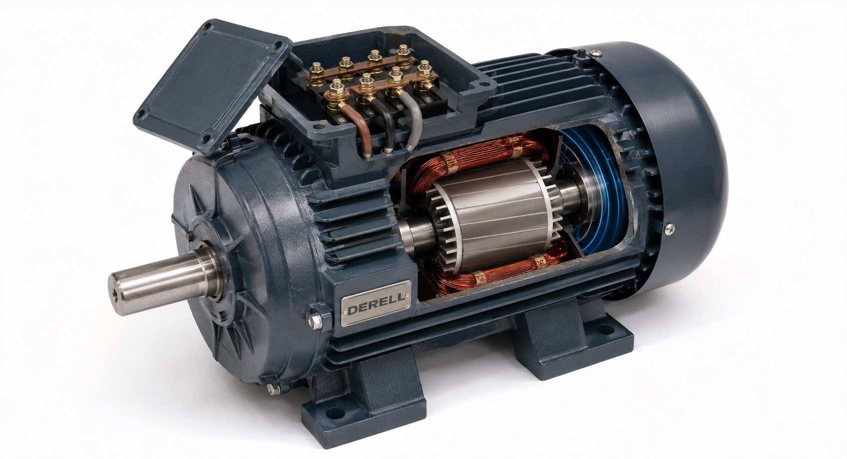
The stator is fixed to the frame; the rotor turns with the shaft. Windings and the magnetic core establish the field, bearings support the shaft, and the frame provides protection and a path for heat. The air gap separates rotor and stator and allows electromagnetic interaction between them.
In a three-phase machine, winding placement and currents separated by 120 electrical degrees create a rotating magnetic field. The physical stator does not rotate. Interaction between that field and the rotor produces shaft torque. The U, V and W terminals identify the motor phase connections; the motor diagram determines the actual wiring.
Watch the field and rotor: slip versus synchronism
Press Start and follow the markers. Blue represents the field; orange represents the rotor. In the induction example their angular separation keeps changing. In the synchronous example it stays fixed. The grey outer ring is the stationary stator. This is a speed comparison slowed by the same scale factor, not a drawing of four-pole winding geometry.
Induction motor: relative motion between the field and rotor conductors induces rotor current. That current interacts with the field to produce torque. During normal motoring, the rotor runs below field speed. The difference is called slip, and it is essential to induction motor operation. In the normal operating region, increasing load generally increases slip.
Synchronous motor: in steady synchronous operation, rotor and field have equal mechanical speeds. Permanent magnets or an excited rotor can provide the rotor field. A synchronous reluctance motor (SynRM) instead uses the rotor’s different magnetic reluctance along different axes. Equal speed does not mean identical angular position. A load-related angular offset can exist; the angle shown is illustrative.
Why a 50 Hz motor may be rated at 1450 rpm
The rotating field’s speed is ns = 120 × f / P, where f is applied frequency in hertz and P is the total number of poles. The result is in rpm. Use pole count, not the number of pole pairs.
At 50 Hz, two, four, six and eight poles give synchronous speeds of 3000, 1500, 1000 and 750 rpm, respectively. An induction motor’s shaft runs below the corresponding field speed during motoring.
For a four-pole, 50 Hz motor rated at 1450 rpm, rated-condition slip is (1500−1450)/1500 × 100 ≈ 3.33%. Another motor or operating load can give a different value. Nameplate speed refers to the shaft under the stated rated conditions.
Single-phase and three-phase motors need different arrangements
Single-phase and three-phase supplies do not imply identical starting arrangements. A stationary single-phase induction motor cannot obtain a preferred starting direction from its main winding alone. An auxiliary winding, often with a motor capacitor, creates the required starting arrangement. Shaded-pole designs are another option. Not every single-phase AC motor uses a capacitor.
A three-phase induction motor gets its rotating field from the phase system and normally needs no starting capacitor. A drive with single-phase input and three-phase output is intended for a compatible three-phase motor; single-phase input does not imply a single-phase motor output.
Speed control is practical with the right drive
On a fixed-frequency supply, speed options are limited. A compatible variable frequency drive (VFD) changes frequency while managing the voltage/current requirements of the motor. Its inverter stage creates the output; many drives use pulse-width modulation. Describing AC speed control as inherently difficult overlooks modern drive systems.
The usable speed range still depends on the torque–speed relationship and motor limits. A shaft-mounted cooling fan moves less air at low speed, so sustained high load may require separate ventilation or reduced loading. Dynamic braking is a separate consideration when the load needs controlled rapid stopping.
Choose for the load, then check the nameplate
The kW rating normally describes rated mechanical shaft output, not electrical input power. Torque and power are related but different: T ≈ 9550 × P / n, with P in kW, n in rpm and T in N·m. A 2.2 kW motor at 1450 rpm therefore delivers about 14.5 N·m at its rated operating point.
Match load torque and starting torque as well as speed, acceleration, duty, mounting and environment. Read the plate’s voltage, frequency, speed, rated current and connection information. Star or delta wiring must match both the supply and the winding rating; neither arrangement is universally correct.
Use the three-phase power and current calculation to interpret readings, and distinguish no-load current from rated-load current. Humming or overheating calls for checks of phase loss, wiring and mechanical load. Protective earth on the frame serves a separate safety function from the motor phase conductors.
Strengths and practical limits
Squirrel-cage induction motors are useful workhorses because of their robust construction and lack of brushes or a commutator. Low maintenance is not zero maintenance: bearings, ventilation, insulation and connections still need attention. Direct-on-line starting can draw high current. Synchronous machines add their own rotor and drive-compatibility requirements.
Manufacturer references
Oriental Motor — AC Motor Fundamentals
Oriental Motor — AC Motor Glossary of Terms
Oriental Motor — Speed Control Methods
ABB — synchronous reluctance motors
ABB — Direct Torque Control and motor types
ABB — effects of variable speed drives on motors
ABB — Softstarter Handbook: nameplate and winding connection