
EN 61009
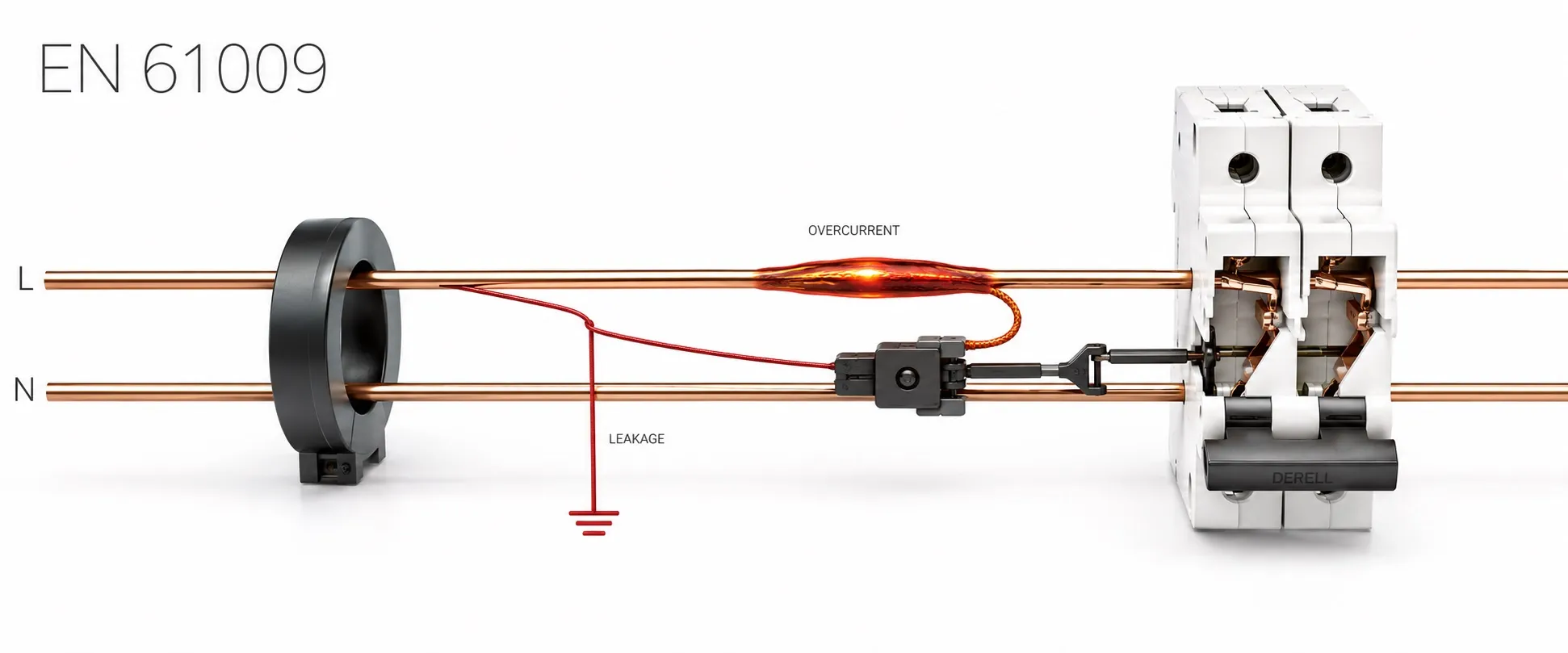
Combining residual-current and overcurrent protection in one device
The EN 61009 series addresses residual current operated circuit-breakers with integral overcurrent protection, known as RCBOs, for household and similar uses. General rules are covered particularly by EN 61009-1. An RCBO combines functions that disconnect a circuit under overload, short-circuit and residual-current conditions. Appropriate selection and installation help reduce electrical risks; they do not eliminate every hazard.
The distinction between MCBs, RCCBs and RCBOs is essential. An MCB covered by EN 60898 provides overcurrent protection, while an RCCB covered by EN 61008 has no integral overcurrent protection. An RCBO combines residual-current protection and overcurrent protection in the same product. In a single-phase circuit, residual-current detection monitors an imbalance between outgoing line current and returning neutral current.
Editor's note: An RCBO's B or C overcurrent curve is a different classification from its Type AC, A, F or B residual-current behaviour. For example, a B-curve RCBO can have Type A residual-current protection. Do not assign the same meaning to a letter used for two different protective functions.
Distinguish the EN edition from the IEC edition
At the catalogue check on 15 October 2026, BSI listed BS EN 61009-1:2012+A13:2021 as current and under review. Internationally, IEC 61009-1:2024 has been published. The year of a new IEC edition must not simply replace the year of the EN reference on a product: European adoption, national publication and applicable amendments require separate checks.
The published scope of IEC 61009-1:2024 covers RCBOs not exceeding 440 V AC, 125 A rated current and 25 kA rated short-circuit capacity, at 50 Hz, 60 Hz or 50/60 Hz. These are scope limits, rather than ratings possessed by every device. The commonly encountered 6–63 A product range is not the limit of the entire standard either.
A, mA and kA answer different questions
The rated current relates to the load circuit, while the rated residual operating current describes residual-current sensitivity. For example, Hager's ADC906R data lists 6 A, C curve, 30 mA, Type A and 6 kA together. The 30 mA marking neither limits the load to 30 mA nor means that the device can never trip below exactly that residual current.
Icn is the rated short-circuit breaking capacity under specified test conditions. Assess it against the prospective fault current and any backup protection arrangement verified by the manufacturer. A higher kA rating does not mean greater residual-current sensitivity. Protective device selection also considers operating voltage, pole arrangement and the manufacturer's conditions of use.
The cable's current-carrying capacity must coordinate with the RCBO's overcurrent characteristic. If starting a load causes tripping, simply changing to curve C or D, or increasing the current rating, is insufficient justification. Assess starting behaviour, cable protection and the required disconnection conditions together.
Match residual-current type to the load and waveform
Type AC, A, F and B residual-current devices respond to different waveforms. Electronic power supplies and variable-speed loads can make selection based solely on sinusoidal residual currents unsuitable. Follow the load manufacturer's specified RCD type and local installation requirements. Type F and Type B also involve supplementary product requirements such as EN 62423.
Additional protection in the 30 mA class does not replace basic insulation or protective earthing. A Type B residual-current classification also does not establish that the device's main circuit is suitable for every DC supply. Verify supply type and breaking capacity separately.
Connection arrangements matter as much as device selection
Each circuit's line and neutral arrangement must follow the selected RCBO's wiring diagram. Incorrectly sharing or mixing neutrals between circuits protected by separate RCBOs can cause unwanted tripping. Neutral and protective conductors are not interchangeable. Pole count alone is also insufficient information: 1P+N does not mean that both poles have overcurrent protection.
Follow LINE/LOAD, input/output and supply-direction markings. In installations with PV inverters, batteries or reverse power flow, establish whether the device is unidirectional or bidirectional. A new version in the same product family being bidirectional does not establish that older versions are too. Switchboard installation and maintenance must also account for busbar compatibility, terminal torque and environmental conditions.
A test button does not replace installation verification
Product testing assesses characteristics such as operating behaviour, short-circuit performance, insulation, temperature rise and endurance. Site verification assesses the safety of the completed installation. A working test button helps check the mechanism's functionality; it does not establish that earthing at a socket has been verified or that all installation measurements have passed.
Evaluate residual-current operating-time measurements using suitable instruments and the applicable installation rules. Test current, waveform, time-delay characteristics and connected loads can affect results. Determine whether overcurrent or residual current caused the trip before declaring the device defective. Investigate repeated operation instead of bypassing protection; replacement work requires authorised personnel, appropriate isolation and verification.
CE marking and the limits of protection
CE marking is not an automatic certificate issued by a central body after EN 61009 testing. The manufacturer is responsible for conformity with applicable EU legislation, technical documentation and the EU Declaration of Conformity. The exact product model and standard edition must match the documentation. Product conformity and correct installation design and verification remain separate assessments.
An RCBO does not automatically include an SPD or voltage monitoring relay. Residual-current protection cannot be relied upon for simultaneous contact with line and neutral where no residual-current imbalance occurs. Combining protective functions in one device does not establish that every electrical risk is covered.
Related guides
Circuit protection, residual current protection and electrical safety
Overview of CENELEC standards
Fuse and protection standards
Fuse products
Sources
BSI: BS EN 61009-1:2012+A13:2021 record and EN/IEC relationship
IEC: IEC 61009-1:2024 scope and technical changes
Hager: ADC906R RCBO ratings and pole arrangement
IET: RCD types and their distinction from overcurrent curves
IET: product testing versus RCD testing in an installation
BEAMA: connection requirements for unidirectional and bidirectional devices
European Union: CE marking, technical documentation and manufacturer responsibility
This overview uses publicly accessible catalogue records, technical data and guidance. Detailed application requires the relevant full standard, local installation rules and manufacturer instructions.