
What is string encoder?
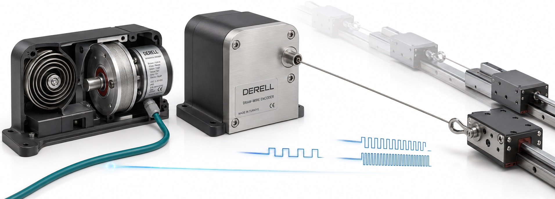
A draw-wire encoder measures linear travel by tracking how much cable a moving part pulls from a spring-loaded drum. Other names include string encoder and wire-actuated encoder. A small housing can therefore monitor the extension of a telescopic assembly, the height of a lifting platform or the position of a machine slide.
The name describes the mechanical measuring arrangement, rather than one universal electrical output. Within the wider family of position sensors, a draw-wire unit may use a rotary encoder, a potentiometer or another sensing element. A string potentiometer is consequently not the same thing as an incremental encoder, even though both can share a similar cable mechanism.
What happens inside the housing?
The housing stays fixed while the measuring cable attaches to the moving object. Outward motion unwinds the drum; a return spring takes up the cable during the return stroke. The sensing element converts drum movement into a signal that the controller can scale to linear position.
It performs a similar measuring task to a linear encoder, but uses a different mechanical path. An optical or magnetic encoder inside the housing does not make the complete assembly contactless: The cable, its attachment and the winding mechanism remain part of the measurement chain.
Choose the output before choosing the controller input
With an incremental encoder, the controller counts pulses on the A and B channels. Their phase relationship identifies travel direction. Position recovery after a power interruption depends on the referencing and count-retention arrangement. An index pulse on a drum that turns several times cannot uniquely identify every position across the full measuring stroke.
An absolute encoder supplies a position code. If the drum makes several revolutions, the system must distinguish those revolutions across the complete measuring range. Interfaces such as SSI or CANopen are available on suitable models. Check the complete system's power-off behaviour rather than assuming that the word “absolute” settles every position-recovery question.
A unit with 4–20 mA or 0–10 V connects to an appropriate analog input. An analog signal may come from a potentiometer with conditioning electronics or from an encoder with analog output. A bare potentiometer provides a resistance-based signal and needs the correct excitation and reading circuit.
Worked example: From pulses to millimetres
Assume a mechanism pays out 200 mm per drum revolution, with an encoder producing 1000 pulses per revolution on channel A. Counting one edge per pulse gives 0.2 mm per count. Evaluating all four A/B edges produces 4000 counts per revolution, giving a nominal step of 0.05 mm per count. Starting from an established zero, 10,000 counts would represent 500 mm of travel.
This calculation describes resolution, not guaranteed accuracy. Accuracy concerns agreement with the actual position; repeatability concerns returning to similar readings at the same position. As a separate hypothetical example, a linearity specification of ±0.1% of a 3000 mm full scale corresponds to ±3 mm for that error component. A display changing in 0.05 mm steps does not establish ±0.05 mm measurement accuracy.
Getting a reliable reading in the PLC
Pulse outputs require a suitable high-speed counter in the PLC. Match the encoder output signal to the receiving electronics. HTL, TTL, push-pull and line-driver outputs have different electrical requirements. A differential RS-422 signal requires a compatible receiver.
At 1000 mm/s, the example above generates 5 kHz on channel A and 20,000 counts per second with ×4 decoding. Check whether the specified counting frequency refers to channel cycles or evaluated edges. Standalone encoder displays and controllers also need the correct input type and scale.
For a sensor configured to map 0–2000 mm onto 4–20 mA, use position = (current − 4) / 16 × 2000, with current in milliamps. A 12 mA reading then represents 1000 mm. Convert PLC raw input values using the module's documented scaling. Monitor out-of-range readings and disconnected wiring separately; an electrically valid current does not prove that the measuring cable is mechanically intact.
Installation determines whether the numbers are useful
Never release the extended cable and let it snap back. Uncontrolled retraction can damage the mechanism. Keep within the rated stroke, avoid kinks and sideways loading at the outlet, and prevent rubbing against sharp surfaces. Use an approved guide pulley where the manufacturer permits a change of direction. The length of a diagonal cable path is not automatically equal to movement along the axis you want to measure.
Check the specified travel speed, acceleration and retraction force. A fast return can produce slack if the mechanism cannot keep up. Inspect the cable, attachment and housing mount, and follow the maker's cleaning and lubrication instructions. An IP protection rating does not establish resistance to cable cuts, welding spatter or ice.
Where does a draw-wire system fit?
Telescopic extension, lift height and machine-slide travel are typical measuring tasks. Compare the required stroke, accuracy, dynamics, interface and environment, then check whether the cable has a protected route. Linear measuring scales may suit guided axes; laser sensors and ultrasonic sensors offer alternatives where the target and operating conditions permit. There is no universal cost or precision advantage.
For a safety-related function, an ordinary position sensor alone does not establish a safe stopping or overtravel system. Mechanical failures, including a broken cable or loose attachment, must be considered alongside the suitability of the sensor and the complete control system.