
what is resolver?
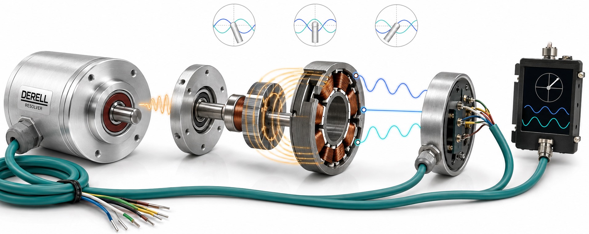
What is a resolver? Position sensing with AC excitation and sin/cos signals
Hello everyone. A resolver is a position sensor that converts shaft angle into electrical information through electromagnetic coupling. It is used in servo motors, industrial motion control and robotics. Two outputs describe shaft position through their sine and cosine relationship.
It serves the same feedback purpose as an encoder, with a different electrical operating principle. A useful resolver–encoder comparison considers accuracy, environmental capability and drive compatibility together. A resolver can provide precise measurements as well as a robust construction.
What do the rotor, stator and windings do?
The rotor turns with the shaft; the stator remains stationary. Rotor position changes the magnetic coupling between excitation and the two sensing channels. A conventional design can have its excitation winding on the rotor and sin/cos windings on the stator. In a variable-reluctance resolver, the windings are on the stator and the rotor geometry changes the coupling. Winding placement is not identical in every resolver.
Brushless designs offer the durability benefits of contactless sensing. Bearings, seals and mounting parts still have operating limits where fitted. Contactless measurement does not make the complete assembly maintenance-free.
Why is AC excitation needed?
Excitation is the AC reference signal that enables measurement. A drive or separate circuit generates it, with frequency, amplitude and current capability matched to the sensor. Excitation frequency is not motor speed. Excitation and output signals can remain AC while the shaft is stationary.
The ideal outputs are Vsin = K × sin(θe) × sin(ωt) and Vcos = K × cos(θe) × sin(ωt). θe is electrical angle, ω is excitation angular frequency, and K combines excitation amplitude with transformation ratio. Angle is carried by the signed amplitude relationship, rather than the carrier frequency. This does not imply that the input circuitry for an analogue sin/cos encoder is compatible.
What do SIN and COS actually mean?
For an ideal one-pole-pair resolver at 0°, the SIN amplitude is zero and COS is positive; at 90°, the opposite applies. At 180°, COS changes sign; at 270°, SIN changes sign. A negative sign means that the corresponding AC output is inverted relative to excitation.
The SIN and COS carriers are not always 90° apart in time. Their sine/cosine relationship describes amplitude as a function of shaft angle. This distinction prevents confusion with the A/B channels of an incremental encoder.
Animation: how does a resolver read shaft angle?
Rotate the shaft, stop it or select an angle. Watch EXC excitation, the SIN/COS outputs and the calculated angle together.
| θe | sin(θe) | cos(θe) |
|---|---|---|
| 0° | 0 | +1 |
| 90° | +1 | 0 |
| 180° | 0 | −1 |
| 270° | −1 | 0 |
Electrical angle: 0.0° · Calculated electrical angle: 0.0000° · Electrical angle error: 0.0000°
Signed amplitudes after demodulation: S = 0.000 · C = 1.000
One pole pair: angle within a turn is unique under ideal conditions.
The plot shows four carrier cycles at the current angle, rather than a time-history record. Dashed lines mark amplitude limits. All channels use the same scale. Excitation is slowed for visibility; the display is not a measurement in hertz or volts.
Two experiments: select Shaft speed = 0°/s and press Start to see AC signals continue while the shaft is stationary. Then select 45°, one pole pair and COS gain = 90%: the calculated angle becomes approximately 48.0128°. This illustrates gain mismatch between channels, rather than a common reduction in both amplitudes.
The ideal model uses θe = p × θm, S = sin(θe), C = g × cos(θe) and θcalculated = atan2(S, C). p is the number of pole pairs and g is the COS gain factor. The result is mapped to 0–360°. RDC tracking dynamics, phase delay, ADC quantisation and random interference are excluded. The shaft drawing shows mechanical angle; with two pole pairs, one electrical-angle reading cannot identify the mechanical sector.
What is an RDC, and how is angle calculated?
A resolver-to-digital converter (RDC) evaluates the excitation reference and sin/cos outputs to produce digital position information. It can be implemented with a dedicated IC or suitable analogue front-end circuitry and software. Applying atan2(S, C) to demodulated values is a useful educational model for distinguishing all four quadrants; an actual converter may use a tracking loop.
Connecting two wires to a general-purpose ADC is insufficient. Input range, differential acquisition, sampling and processing synchronised with the reference must suit the signal. Likewise, a digital input or high-speed counter on a PLC cannot directly decode raw resolver outputs.
Does a resolver provide absolute position?
With one pole pair, sin/cos information distinguishes angle within a mechanical revolution. Once excitation and reading resume, the current angle can be obtained; the sensor does not inherently retain the number of completed turns. Its coverage therefore differs from that of a multiturn absolute encoder.
With two pole pairs, electrical angle repeats twice per mechanical revolution: mechanical positions of 0° and 180° can produce the same electrical angle. The drive setting must match the resolver pole-pair count. An absolute reading within a turn does not, by itself, establish the correct machine datum or motor commutation offset.
How should resolution and accuracy be assessed?
Resolution describes the digital step size; accuracy describes deviation from the actual angle. For example, encoding electrical angle in 12 bits gives an ideal step of 360° / 4096 ≈ 0.08789°. At 16 bits, the step is approximately 0.00549°. Bit depth does not guarantee overall measurement accuracy.
Sensor error, channel gain matching, phase delay, installation and converter behaviour all contribute. The animation's 10% COS gain reduction demonstrates how an apparently present signal can still produce an incorrect angle. When load position is critical, motor-shaft feedback and linear measurement at the load must also be considered separately.
Does a rugged resolver resist all interference?
No. Suitably designed resolvers can handle demanding temperature and vibration conditions; use the product specifications to establish the limits. Noise, channel imbalance and incorrect shield connections can cause angle errors or feedback faults. Errors are not always small amplitude changes, and filtering cannot remove every cause.
Differential signal pairs, suitable cables/connectors, routing away from power wiring and manufacturer-specified shielding all matter. Couplings and mounting arrangements influence mechanical errors and loads. When considering another feedback design, such as a hollow-shaft encoder, assess mechanical compatibility separately.
Which specifications must match the drive?
Match excitation voltage/frequency, transformation ratio, pole pairs, pin assignments, input signal range, permitted speed and operating temperature. The RPM limit is separate from excitation frequency. Depending on the converter, diagnostics may also detect missing signals or loss of tracking.
A resolver input is not automatically compatible with inputs for other encoder output types. TTL/HTL, line-driver and EnDat describe other electrical or communication interfaces. A pulse input's counting frequency rating cannot be used to select resolver excitation either.
Technical sources: Analog Devices — resolver construction · Analog Devices — RDC circuitry · Analog Devices — signal errors · TI — excitation and measurement chain · Moog — brushless resolvers.