
What is Pneumatic encoders?
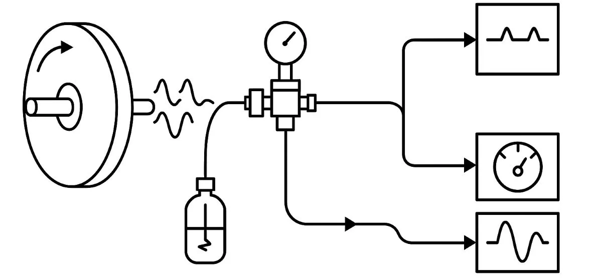
What is a pneumatic encoder? Air-based position and speed sensing
Hello everyone. Pneumatic encoder can describe a specialized arrangement that encodes position through changes in air pressure or flow. An encoder converts movement into measurable information; air can carry that information. However, the term does not describe the same sensor construction in every catalogue.
Start with one distinction: does air perform the sensing, or does it simply move the measuring tip? The answer helps identify the measurement principle and the interface to the control system.
Different constructions can share a similar name
| Construction | Role of air | Measurement information |
|---|---|---|
| Pneumatic encoding / sensing | Producing position-dependent pressure or flow changes | Pressure level, pulses or a code |
| Pneumatic-push encoder probe | Extending the measuring tip towards a component | An optical or other electrical measurement system |
| Encoder in a pneumatic motion system | Driving the motor or cylinder | Signals from a separate encoder |
For example, air pressure can extend a pneumatic-push linear encoder probe while an optical scale measures its position. Research designs also use pressure sensors to read volume changes in sealed, flexible air chambers and calculate angular and linear displacement. Not every pneumatic sensing system uses a slotted disc.
How does the slotted-disc and nozzle example work?
In a simple teaching arrangement, air passes through a restrictor to a nozzle. When a slot aligns with the nozzle, air escapes more easily and back pressure falls. When a solid section blocks the air path, back pressure rises. Suitable sensing circuitry can convert the pressure changes into pulse information.
This is a back-pressure sensing example; an opposed-air-jet arrangement or another pneumatic circuit may produce a different signal relationship. Flow measurement and pressure measurement also concern different quantities. A nozzle–flapper principle alone does not constitute an encoder; continuous position measurement requires suitable encoding and signal evaluation.
PPR, frequency and position information
In an ideal single-channel model where each slot produces one complete pulse period, PPR equals the number of slots per revolution. The frequency is f = PPR × RPM / 60. At 24 slots and 180 RPM, the theoretical frequency is 72 Hz and the slot pitch is 15°. This pitch is not a measurement-accuracy guarantee.
Pulse counting can support incremental position calculations. A single channel cannot determine rotation direction on its own; a suitable second channel or other information is needed. Counting pulses does not automatically provide absolute position either. The initial position, reference and any missed pulses require separate consideration.
Interactive model: airflow and pulse generation
A single-channel teaching model with a slotted disc, restrictor and nozzle. Press “Start” to watch it rotate, then change speed and slot count. Changing the slot count represents a different disc design, not software PPR programming on a real device.
Initial example: 24 slots × 180 RPM / 60 = 72 Hz. The counter below shows completed ideal pulse periods in the slowed model.
180 RPM · 24 PPR · 72 Hz
Ideal period count: 0 · Visual slowdown: ×18
Air path open → low back pressure
Ideal normalized back pressure: 0 = open air path, 1 = blocked air path. This two-level plot is not a measured pressure signal.
The animation slows automatically to keep pulses visible; Hz is calculated from the selected actual RPM. The model does not calculate air compressibility, tubing delay or sensor thresholds. Real pressure transitions may differ from this ideal square wave.
Which signal does a PLC count?
A PLC cannot count an air tube directly. A sensor or converter with adequate response speed must turn pressure changes into electrical pulses. Check converter response time, pulse width and the receiver's counting frequency together. A high-speed counter cannot recover a pulse that the sensor never produced.
For digital connections, NPN/PNP and NO/NC operation must match the input. An analogue pressure transmitter reports pressure; pressure-to-current conversion alone does not make a 4–20 mA output proportional to shaft speed. Speed requires evaluating the pulses over time.
Why do air quality, tubing and installation matter?
Nozzle clearance, supply stability, leaks and tubing volume affect measurement behaviour. Changing tube length or diameter can alter the response; a larger tube is not automatically faster. When measuring pressure at supply and signal points, compare bar, kPa and other pressure units correctly.
Select filtration and regulation for the product's air requirements. Follow the manufacturer's lubrication instructions and avoid adding a lubricator by default. Blocked nozzles, water or oil backflow and loose connections can disturb the signal. Check shaft alignment where a coupling is used, and cables and connectors on electrical converters.
Dust, water and temperature ratings depend on the model. An electrically passive sensing head does not establish that the entire system is free of ignition risks. Pressure sensing and counting equipment may still be electrical. Using air does not guarantee unlimited environmental resistance or suitability for explosive atmospheres.
Technical sources: Festo — pneumatic sensing · SMC — air-sensing operating conditions · Solartron — optical pneumatic-push probes · Scientific Reports — pneumatic position-sensor research.