
EN 60898
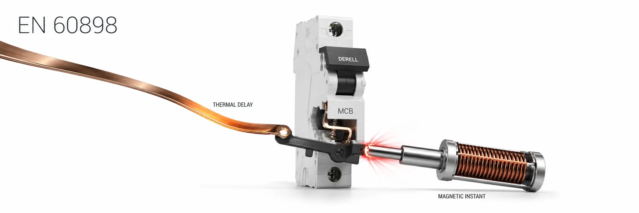
Select a circuit breaker using more than its current rating
The EN 60898 series addresses circuit breakers providing overcurrent protection for household and similar installations. Widely used miniature circuit breakers, or MCBs, fall within this framework. Although everyday terminology can blur the distinction, fuses and circuit breakers are different devices. An appropriately selected MCB protects its circuit against the effects of overloads and short circuits.
EN 60898-1 covers AC operation. Its stated scope includes devices at 50 Hz, 60 Hz or 50/60 Hz, with ratings not exceeding 440 V between phases, 125 A and 25 kA short-circuit capacity. These scope limits are not the ratings of every product. A 6 kA MCB does not become a 25 kA device simply because it complies with this standard.
Editor's note: In C16, 16 indicates the rated current and C identifies the tripping characteristic. It is not a current limiter that trips instantly whenever current rises slightly above 16 A. Rated current, tripping curve and short-circuit breaking capacity are three separate selection criteria.
Overloads and short circuits produce different responses
In a thermal-magnetic MCB, the thermal release responds to heating caused by overload, while the magnetic release responds to high fault current. Overload operation is time-dependent: greater current generally produces faster tripping. During a short circuit, sufficiently high current causes rapid magnetic operation. These operating regions should not be reduced to a single current threshold.
The magnetic tripping bands are 3–5 × In for curve B, 5–10 × In for curve C and 10–20 × In for curve D. For a 16 A device, these correspond to 48–80 A, 80–160 A and 160–320 A. They describe the magnetic operating region, not permissible continuous load current; use the manufacturer's time-current curve to assess the complete response.
Changing from B to C or D to tolerate starting current also raises the fault current needed for rapid magnetic operation. For motors and other high-power loads, tolerating starting current does not meet every motor protection requirement. A curve change requires verification that the necessary fault disconnection time remains achievable.
Coordinate the load, cable and protective device
Select the rated current together with the load's operating and starting characteristics and the cable cross-section. One initial check is IB ≤ In ≤ Iz: IB is design load current, In is device rated current, and Iz is cable current-carrying capacity after installation and environmental corrections. This relationship does not replace short-circuit withstand and disconnection-time checks.
For long circuits, consider fault-loop impedance as well as voltage drop. If fault current is insufficient, the chosen curve's rapid operating condition may not be achieved. Fitting a higher current rating to prevent repeated tripping can compromise cable protection. Investigate the load, connections and circuit design first.
The kA rating is not load capacity or tripping sensitivity
Icn is rated short-circuit breaking capacity. Compare it with the prospective fault current at the installation point. Where the device is insufficient on its own, use only an upstream protection combination verified by the manufacturer. The presence of an upstream fuse does not automatically provide adequate backup protection for every downstream device.
One product can have different ratings under different standards. Schneider Electric publishes 6 kA under EN/IEC 60898-1 and 10 kA under EN/IEC 60947-2 for its A9F73106. Icn and Icu belong to different testing frameworks; read the standard, operating voltage and pole arrangement together. Protective device selection cannot simply use the largest number in a catalogue.
Selectivity requires separate assessment. Ideally, a fault on an outgoing circuit disconnects only that circuit, but different upstream and downstream current ratings do not guarantee this. Where the main breaker trips before an outgoing breaker, investigate time-current characteristics and manufacturer coordination data.
An MCB does not replace residual-current protection
MCBs, RCCBs and RCBOs perform different functions. An RCCB covered by EN 61008 detects residual current and has no integral overcurrent protection. An RCBO covered by EN 61009 combines residual-current and overcurrent protection. Do not assume that an ordinary MCB provides residual-current protection at 30 mA.
An MCB's B curve is different from an RCD's Type B classification. An appropriate MCB also does not remove the need for protective earthing, equipotential bonding or installation verification. Automatic disconnection under fault conditions depends on the device and installation working together.
Verify AC or DC suitability against the relevant part and ratings
60898-1 addresses AC operation, while 60898-2 addresses AC and DC operation. AC voltage and breaking-capacity ratings cannot simply be transferred to a DC circuit. For DC protection, check operating voltage, breaking capacity, polarity and the manufacturer's required pole connections. Arbitrarily connecting two poles in series does not make every device suitable for a higher DC voltage.
Installations involving PV, batteries or reverse power flow also require verification of unidirectional or bidirectional suitability. Follow LINE/LOAD and input/output markings. One version in a product family being bidirectional does not establish that every version has this capability.
Assembly conditions and verification complete the selection process
Thermal-magnetic devices for household and similar applications generally have ratings associated with a 30 °C reference ambient temperature. Hot enclosures and mutual heating between adjacent devices can affect behaviour; apply the manufacturer's correction tables. Switchboard installation and maintenance must assess busbar compatibility, terminal torque, conductor capacity and temperature conditions together.
Product tests assess operating behaviour, temperature rise, insulation, short-circuit performance and endurance. Installation verification checks selection, connections and the required measurements. A continuity check alone does not verify an MCB's tripping curve or breaking capacity. Replacement and connection work requires authorised personnel, appropriate isolation and verification.
Read edition references and CE marking correctly
At the catalogue check on 15 October 2026, BSI listed BS EN 60898-1:2019+A11:2024 as current. IEC presents its consolidated publication as IEC 60898-1:2015+A1:2019. The dates of the EN edition, IEC edition and local adoption are not interchangeable.
CE marking is not an automatic certificate issued by a central body following EN 60898 testing. The manufacturer assesses conformity with applicable legislation, prepares technical documentation and issues the EU Declaration of Conformity. Product conformity alone does not establish that the completed assembly or installation has been designed correctly.
Related guides
IEC 60898
CENELEC standards
Fuse and protection standards
Circuit protection, residual current protection and electrical safety
Fuse products
Sources
BSI: BS EN 60898-1:2019+A11:2024 scope and publication status
IEC: consolidated IEC 60898-1:2015+A1:2019
IEC: IEC 60898-2:2016 scope for AC and DC operation
ETI: thermal-magnetic operation and B, C, D tripping curves
Schneider Electric: EN 60898-1 and EN 60947-2 ratings on one product
BEAMA: supply connections for unidirectional and bidirectional devices
European Union: CE marking and manufacturer responsibility for conformity
This overview uses publicly accessible scope information, catalogue records and technical guidance. Detailed application requires the full standard, local installation rules and manufacturer instructions.