
Differences Between Grounded, Ungrounded and Exposed-Junction Thermocouples
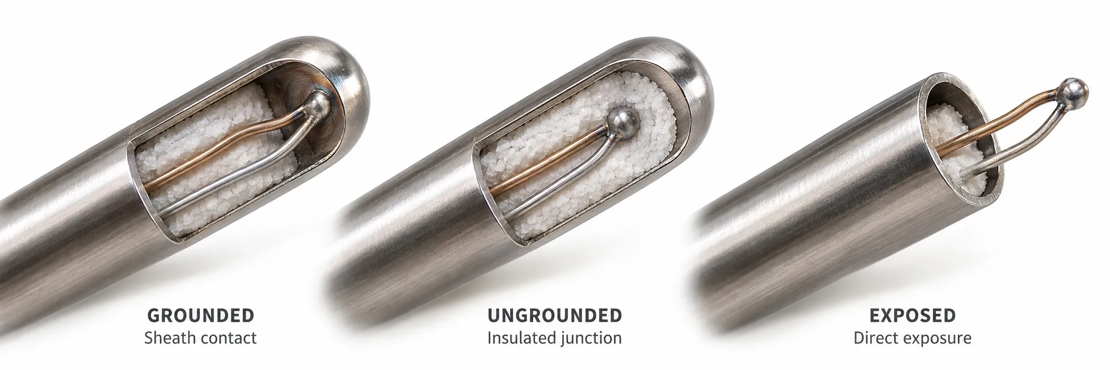
Balancing response, isolation and protection at the sensing tip
A thermocouple's grounded, ungrounded or exposed junction describes how its measuring junction relates to the metal sheath and process medium. Thermocouple type and junction construction are separate choices: a Type K or Type J sensor can use any of these arrangements. The main differences concern response time, electrical isolation and resistance to process conditions.
A grounded junction is connected to the sheath; an ungrounded junction is electrically insulated from it; an exposed junction contacts the medium directly. Choosing the fastest sensor is only part of the decision: the process and measurement electronics also matter.
Editor's note: “Grounded” here means that the measuring junction is electrically connected to the metal sheath. Connecting that sheath to the installation's protective earth, PE, is a separate installation issue. Selecting an ungrounded sensor does not remove the machine's protective earthing requirements.
Grounded junction: a short thermal path and an electrical connection
In a grounded thermocouple, the measuring junction formed by the two conductors is welded to the sheath tip. This metal contact improves heat transfer to the junction. With comparable diameter and construction, it usually responds faster than an ungrounded design. It can be useful where a changing fluid temperature must be measured quickly while retaining sheath protection.
The weld also creates an electrical path. If the sheath is connected to process equipment and the instrument uses another ground reference, a potential difference can produce a ground loop. A grounded sensor does not automatically create a loop; the complete circuit determines whether one exists.
Ungrounded junction: electrical separation from the sheath
An ungrounded junction is not welded to the sheath. In mineral-insulated sensors, the conductors and junction are typically separated from it by an insulating material such as magnesium oxide. IEC 61515 addresses mineral-insulated metal-sheathed thermocouple cables and thermocouples.
This construction removes the direct conductive connection from the process sheath to the measurement circuit. It can help when equipment has different ground potentials. However, heat must pass through the sheath and insulation, so response is generally slower than with an equivalent grounded design. Electrical isolation does not provide immunity to every source of interference.
Exposed junction: fast response with limited protection
An exposed junction extends beyond the sheath or is left open to the medium without a protective sheath. Direct contact and low thermal mass are useful for rapid temperature measurements in air and clean gases. Laboratory experiments and air duct tests are typical examples.
The junction is more vulnerable to impact, abrasive particles and chemical attack. It should not be the automatic choice for corrosive gases, high pressure or conductive liquids. Liquid use requires suitable chemical compatibility, electrical conditions and manufacturer process ratings. A conductive medium can also impose its electrical potential on the exposed junction.
Why response rankings are only a starting point
Under comparable conditions and dimensions, exposed junctions usually respond fastest, followed by grounded and then ungrounded designs. However, probe diameter, sheath thickness, flow velocity, immersion depth and installation can outweigh that trend. A thin ungrounded probe may respond faster than a thick grounded probe.
A thermowell adds metal mass and thermal resistance between the process and sensor. Its geometry and contact with the probe can strongly influence the total response. When selecting temperature sensor accessories, consider mechanical strength and thermal contact as well as the connection dimensions.
Noise and ground loops in machines using VFDs
Variable frequency drives, servo drives and switched power circuits can couple electrical noise into measurement wiring. Thermocouple signals are small. Temperature jumps when a motor or heater switches on, unstable readings or a persistent offset warrant investigation of wiring and ground references. These symptoms alone do not prove that a ground loop exists.
On a PLC input module, channel-to-earth, bank and channel-to-channel isolation are different arrangements. Grounded sensors attached to different process bodies may interact if their channels share a reference within one bank. A differential input does not itself provide galvanic isolation; the permitted common-mode voltage must also be checked.
An isolated temperature transmitter can help break an unwanted conductive path when its isolation arrangement suits the application. A 4–20 mA output does not prove that galvanic isolation is provided. Separate thermocouple wiring from motor output cables, use appropriate shielding and follow the manufacturer's connection instructions. Do not assume the same shield termination arrangement suits every installation.
Accuracy, cold junction compensation and cable selection
Junction construction alone does not determine the sensor's tolerance class. IEC 60584-1 specifies temperature–EMF reference functions and tolerances; ITS-90 reference tables describe the thermoelectric characteristics of the type. Grounded and ungrounded sensors of the same type and class can meet the same tolerance requirements under suitable conditions.
All three designs require cold junction compensation. Changing junction construction will not correct an incorrect type setting or unsuitable cable. Consider the difference between extension and compensating cables, polarity and connection temperatures; IEC 60584-3 covers the relevant cable requirements.
Actual measurement uncertainty includes contributions from installation, heat conduction, electrical noise and the instrument as well as sensor tolerance. Faster does not automatically mean more accurate. The Pt100 versus thermocouple comparison concerns a separate choice of sensor technology.
Field identification and practical selection
Start with the manufacturer's documentation and order code. With the sensor de-energized and disconnected from the electronics, a resistance check between the conductors and sheath can provide supporting evidence. A grounded junction normally shows a low-resistance connection; a healthy ungrounded design should show high resistance. However, no continuity on a multimeter does not prove adequate insulation at every temperature. Moisture, crushing or insulation damage can cause unintended sheath contact in an ungrounded sensor; use the manufacturer's specified test conditions.
Consider a grounded design when fast response and sheath protection are needed, an ungrounded design when electrical separation from the sheath is a priority, and an exposed junction for very rapid measurements in clean air or gas. Pressure, chemical environment, installation and the input characteristics of the temperature controller determine the final choice.
Related topics
How thermocouples work
Thermocouple types
Cold junction compensation
Mineral-insulated thermocouples
Thermocouple system measurement uncertainty
Sources
Omega: thermocouple junction styles
WIKA: sheathed thermocouples and junction construction
NI: isolation types in measurement systems
NI: field wiring and noise in analog signals
IEC 60584-1: reference functions and tolerances
IEC 61515: mineral-insulated metal-sheathed thermocouples
NIST: ITS-90 thermocouple reference data