
EN 60269
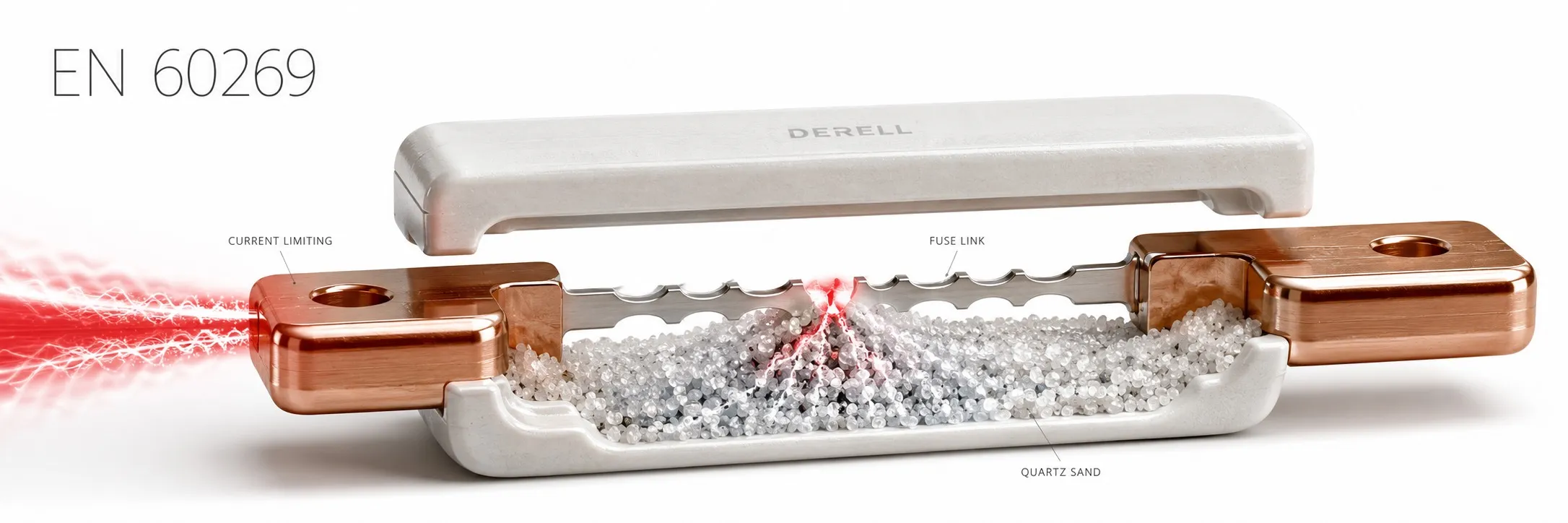
A fuse is defined by more than its current rating
The EN 60269 family addresses the characteristics and test requirements of low-voltage fuses with fusible elements. The function of an electrical fuse, when correctly selected, is to interrupt overcurrent and limit its effects on protected conductors and equipment. The family extends beyond household applications, with different parts addressing industrial distribution, motor circuits, power electronics, photovoltaic systems and batteries.
The fuses discussed here differ from resettable circuit breakers. Operation melts the element, and the fuse-link must be replaced. The fuse-link, carrier and base are also separate components; suitability involves more than the ampere marking on a cartridge.
Editor's note: A 32 A gG fuse and a 32 A aM fuse provide different protection. gG is a full-range general-purpose category, while aM addresses short-circuit protection of motor circuits. An aM application requires separate overload protection. Identical dimensions and current ratings do not establish interchangeability.
Which part addresses which application?
The international foundation is the IEC 60269 family; read European and national adoption designations together with their part and edition. 60269-1 provides general requirements. 60269-2 addresses fuse systems operated by authorized persons, mainly for industrial applications. 60269-3 addresses systems operated by unskilled persons, mainly for household and similar applications.
60269-4 addresses semiconductor protection, 60269-6 photovoltaic systems, and 60269-7 batteries and battery systems. IEC TR 60269-5 provides application guidance; it is not another utilization category. Assess each part's scope and referenced editions separately.
IEC 60269-1:2024 covers fuses incorporating enclosed current-limiting fuse-links with rated breaking capacities of at least 6 kA, intended to protect power-frequency AC circuits not exceeding 1,000 V or DC circuits not exceeding 1,500 V. These scope limits do not give every product a 1,000 V AC or 1,500 V DC rating. Miniature appliance fuses are addressed by other families, such as IEC 60127.
Separate rated current, voltage and breaking capacity
Rated current, In, describes current carrying under specified conditions; it is not an instantaneous operating threshold whenever exceeded slightly. The time-current characteristic describes expected operation at different overcurrents. Rated voltage concerns the voltage conditions for the applicable AC or DC duty. Breaking capacity describes the prospective fault current that can be safely interrupted under stated conditions.
For example, 32 A and 120 kA markings serve different purposes: 32 A is the normal current rating, while 120 kA is not permissible continuous load current. If the prospective short-circuit current is 50 kA, a fuse rated to interrupt 20 kA at the applicable voltage and circuit conditions is insufficient on its own. Any backup protection requires a verified device combination.
Cable protection requires more than In ≤ Iz
Select the fuse together with the cable cross-section. Basic overload protection checks include IB ≤ In ≤ Iz and I2 ≤ 1.45 × Iz. IB is design load current, Iz is corrected cable current-carrying capacity, and I2 is the current ensuring operation of the protective device within the specified time. For a fuse, the applicable conventional fusing current is used.
Simplified example: take IB = 25 A, Iz = 32 A and In = 32 A. The first relationship is satisfied. If the applicable fuse data specifies I2 = 1.6 × In, however, I2 is 51.2 A, while 1.45 × Iz is 46.4 A. The second check fails. This explains why matching a “32 A cable” with a 32 A fuse is insufficient by itself. Actual selection also requires verification of disconnection time, short-circuit withstand, ambient conditions and installation method.
How to read gG, aM, aR and gR markings
g identifies a defined full breaking range, while a identifies a defined partial breaking range. They are not simply two speed labels meaning “very fast” and “slow”. gG provides general-purpose overload and short-circuit protection. aM addresses short-circuit protection of motor circuits; starting current and duration must be considered, with separate overload protection coordinated into the circuit.
aR is a partial-range category for power semiconductors; safe interruption of low overcurrents must not be assumed. gR is a full-range semiconductor category. For a drive or rectifier, use the manufacturer's specified category, part number and coordination data rather than simply requesting a “fast fuse”. A suitable input fuse does not guarantee that the semiconductor will survive every IGBT fault.
I²t and peak current describe the stress passed downstream
Pre-arcing I²t integrates current squared over time up to element melting; total clearing I²t also includes the subsequent arcing period until interruption is complete. Its unit is A²s, not directly joules, and it relates to conductor thermal stress. Semiconductor coordination compares the fuse's total clearing data with the device's withstand capability under compatible conditions; pre-arcing data cannot substitute for total clearing data.
Current limitation can reduce the prospective peak at sufficiently high fault currents. It does not hold normal load current at a fixed value. Assess peak let-through current, total I²t and arc voltage together, particularly when protecting sensitive power electronics.
Verify AC, photovoltaic and battery duties separately
When selecting a DC fuse, an AC marking cannot be transferred directly. For example, one Mersen gG family is specified at 415 V AC and 240 V DC. Its 415 V AC marking does not establish suitability at 415 V DC. DC interruption depends on voltage, circuit L/R time constant and the current range to be interrupted.
gPV is a category developed for photovoltaic applications; 60269-6 gives supplementary requirements for PV strings and arrays. Part 60269-7 addresses batteries and battery systems up to 1,500 V DC. Suitability for PV duty does not establish suitability for every battery fault condition. Verify voltage, minimum and maximum prospective fault currents and manufacturer data for each application.
The holder and upstream protection also matter
For a fuse-holder, check dimensions, contact arrangement, rated voltage, current and acceptable power dissipation. Form factors such as NH, D/D0 and cylindrical do not replace utilization categories. A loose or damaged contact can cause local overheating even when the fuse-link is correctly selected. Follow manufacturer instructions for tightening torque and panel operating temperature.
Selectivity means a fault on an outgoing circuit does not unnecessarily operate upstream protection. If the upstream device operates first, examine time-current bands and short-circuit I²t coordination, not just the difference in current ratings. Ratios such as 1.6 used for certain gG combinations are not universal rules for different categories and every product. Use manufacturer selectivity and backup protection tables.
What do test reports and replacement checks establish?
Characteristics assessed include insulation, temperature rise, power dissipation, time-current behaviour, breaking capacity and current limitation. Relevant type tests and markings establish product characteristics. Correct circuit selection and installation still require separate verification.
Investigate why a fuse operated; the replacement fuse-link must meet the same application requirements. A continuity test can indicate an open element but does not verify breaking capacity or the time-current characteristic. Perform replacement after isolating the circuit and verifying absence of voltage. An ordinary fuse-carrier must not be used as a load-breaking switch.
A fuse-link differs from an EN 60898 circuit breaker and does not replace residual-current protection. Design the protective arrangement around the function of each device.
Read the edition and conformity information correctly
At the 15 October 2026 check, BSI lists BS EN IEC 60269-1:2025 as current; the international publication is designated IEC 60269-1:2024. State the part, edition and applicable amendments clearly in specifications. EN and IEC designations should not be treated as one document without checking edition information.
CE marking is not an automatic certificate issued after a single EN standard test. The manufacturer identifies applicable product legislation, assesses conformity and prepares technical documentation and the required EU Declaration of Conformity. A statement of “EN 60269 compliance” alone does not demonstrate completion of all those responsibilities.
Related guides and products
Fuse types and basic concepts
Fuse standards
IEC fuse standards
CENELEC fuse standards
Fuse products
Sources
IEC: scope of IEC 60269-1:2024
BSI: BS EN IEC 60269-1:2025, general requirements and tests
BEAMA: low-voltage fuses, utilization categories and selectivity
Mersen: cable and motor protection with gG and aM fuses
Eaton Bussmann: semiconductor protection, I²t and DC applications
Mersen: 415 V AC and 240 V DC ratings within one fuse family
IEC: IEC 60269-6:2010+A1:2021, photovoltaic fuses
IEC: IEC 60269-7:2021, fuses for batteries and battery systems