
When selecting a servo motor
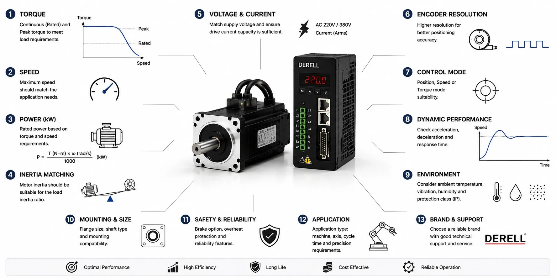
Size the load, motion profile and drive as one system
Selecting a servo motor requires more than matching its power rating or flange size. The motor must deliver the required torque and speed throughout the duty cycle and settle at the target position within the specified time. Assess motor and servo drive compatibility, the transmission, feedback and operating environment together.
Define the motion profile first
Specify the load mass, transmission mechanism, travel distance, cycle time, acceleration and deceleration times, dwell periods and settling time. Horizontal transport, vertical lifting and rotary indexing require different calculations. For an axis requiring high dynamic performance, maximum speed alone is insufficient: you also need the time available to reach it and the number of moves per minute.
Continuous torque, peak torque and RMS torque
Load torque comes from friction, gravity and process forces. Acceleration torque depends on total inertia and angular acceleration. With every quantity referred to the same motor shaft, a basic relationship is T = Jeq × α + Tload, where Jeq includes rotor inertia. Account for direction and force signs; compare the torque obtained from the dynamic calculation with the operating limits of speed and torque control.
Peak torque is available only within permitted time and current limits. RMS torque helps assess cycle heating: TRMS = √[Σ(Ti2 × ti) / Σti]. A dwell period is not a zero-torque interval if the motor holds a load. RMS sizing is an initial check; speed, cooling and manufacturer thermal limits must also be verified.
Read speed and power ratings together
Rated speed and maximum speed are different specifications. Do not assume the highest catalog torque and speed are available simultaneously: operating points must remain inside the motor-drive pair's torque-speed envelope. Mechanical power follows P(kW) = T(Nm) × n(rpm) / 9550. For example, 750 W at 3000 rpm corresponds to approximately 2.39 Nm of rated torque; this alone does not establish acceleration capability.
Convert linear speed into motor speed. A directly coupled ball screw with a 10 mm/revolution lead requires 3000 rpm to produce 500 mm/s. A gearbox changes the required motor speed according to its ratio. An axis holding a load at standstill can draw current and generate heat even though its mechanical output power is zero.
Refer load inertia to the motor shaft
Do not compare rotor inertia directly with the physical load inertia before calculating reflected load inertia. Defining i = motor speed / load speed, an ideal transmission gives Jload,reflected = Jload / i2. A 4:1 reduction therefore divides the load's reflected inertia by 16; gearbox, coupling and other component inertias must also be included.
Motor and load inertia do not have to match at 1:1. An acceptable ratio depends on mechanical stiffness, backlash, required bandwidth, drive tuning and manufacturer limits. Increasing the reduction ratio also increases motor speed. An unnecessarily large rotor can add inertia that must itself be accelerated, as well as cost.
Thermal capacity and operating conditions
Distinguish continuous stall torque, continuous torque at rated speed and short-duration peak torque. Ambient temperature, altitude, heat transfer through the mounting flange and ventilation affect usable continuous torque. Do not assume the full catalog rating is available unless the mounting and cooling conditions specified for servo motor thermal management are met.
Encoder resolution, accuracy and repeatability
Encoder or resolver feedback must match the type and interface supported by the drive. Resolution describes the measurement increment, accuracy describes deviation from the true position, and repeatability describes returning to the same position under the same conditions. For example, 20-bit single-turn position data provides 1,048,576 discrete values; it does not guarantee equivalent machine accuracy.
Screw lead error, gearbox backlash, coupling compliance, temperature and deformation under load affect actual positioning accuracy. Reaching the target matters, but so does the time needed to remain within the specified error band. Where necessary, consider additional load-side measurement and a control architecture that supports it.
Check the motor, drive and controller combination
Keep the drive's mains input voltage separate from the motor winding and terminal voltage limits. Verify continuous and peak current, RMS versus peak current conventions, feedback protocol, temperature sensor, brake supply, cables and pin assignments. Two motors with the same power rating may not be interchangeable. Check motor identification and drive parameter compatibility during selection.
Pulse/direction, analog commands and industrial networks primarily define the controller-to-drive interface; they are distinct from the motor encoder connection. If multi-axis synchronization is required, include cycle time, timing synchronization and the controller's motion functions in the selection.
Mechanical mounting and cabling
Check flange and pilot dimensions, shaft diameter, keyed or plain shaft options, coupling attachment and permitted radial and axial loads. Applying belt tension directly to the motor bearings can reduce service life. Oil, washdown fluids, dust and moving-cable conditions affect shaft seal, connector and cable selection. Power and feedback cable routing, shielding and grounding also matter for noise suppression and signal filtering.
Braking energy and vertical-axis safety
Rapid deceleration or a descending load can return regenerative braking energy to the drive's DC bus. Check energy absorption capacity, braking resistance or a suitable regenerative unit against the duty cycle. A motor holding brake serves a different purpose; most standard holding brakes are not intended for repeated dynamic stopping during normal operation.
For vertical axes, assess brake torque, engagement and release delays, and secure load retention separately. STO prevents motor torque generation; it does not independently prevent a falling load or provide electrical isolation. Determine the necessary safety brake and other measures from the application risk assessment and manufacturer instructions.
A short duty-cycle example
Suppose an axis operates at 8 Nm for 0.2 seconds, 2 Nm for 0.6 seconds, −6 Nm for 0.2 seconds and 0 Nm for 1 second. Over this two-second cycle, TRMS ≈ 3.35 Nm and the largest absolute torque is 8 Nm. Squaring negative torque makes its RMS contribution positive. The proposed motor-drive pair must support both the thermal demand and the short-duration 8 Nm demand at the corresponding speeds. This example excludes application losses and uncertainty margins.
Before ordering and during commissioning
Specify load and transmission data, torque-speed requirements, duty cycle, target accuracy, motor and drive part numbers, feedback, brake and cables together. During commissioning, monitor current, temperature, following error and settling time with the heaviest load and most demanding cycle. Accessible connections and appropriate cable routing simplify maintenance and repair; correct sizing and a suitable motion profile also support energy efficiency.
Related servo topics
Use the servo FAQ for the broader subject and basic servo system components for the complete system structure.
Compare servo motors and stepper motors, then explore servo position control and selection between servo motor types for application-specific decisions.
Other topics that complete the selection
On the control side, review PLC functions and EtherCAT communication; on the feedback side, review how rotary encoders work.
For site conditions, check IP protection ratings; for deceleration energy, check the role of a braking resistor. A resistor must meet the resistance and power limits specified for the selected servo drive.