
What is PLC Instruction List (IL)?
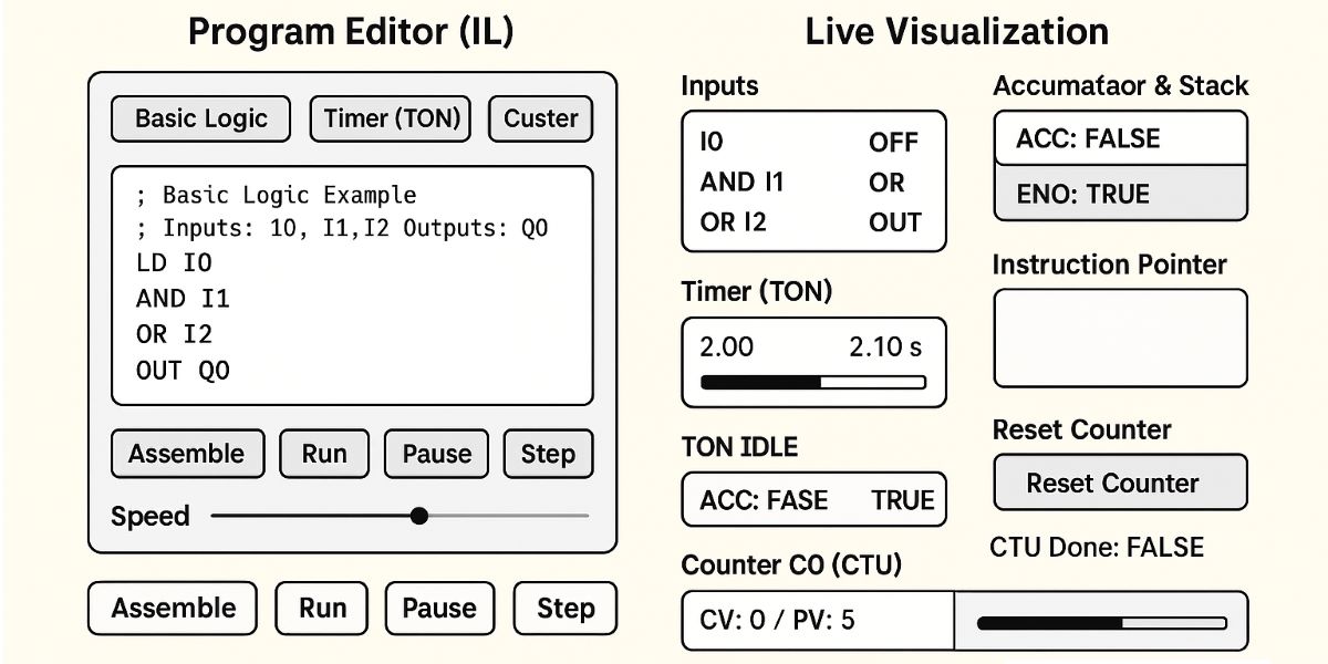
What is PLC Instruction List (IL)? Instruction List is a text-based programming language for PLCs, using short instructions written on separate lines. In PLC programming, it has been used to evaluate input conditions, perform calculations and store results in variables. Its instruction-oriented structure resembles low-level assembly languages.
IL and the standard: IL appeared in earlier editions of IEC 61131-3. It is absent from the language suite in the 2025 edition, which defines Structured Text (ST), Ladder Diagram (LD) and Function Block Diagram (FBD). SFC structures programs using steps and transitions. An older tool offering IL support does not mean IL belongs to the current standard's language suite.
Why learn IL today? It remains useful for reading automation projects on older machines, investigating faults and migrating software to another platform. For a new project, consider hardware support, the maintenance team's skills and long-term maintainability when selecting a language. Short instructions do not automatically make a program faster or easier to understand.
How it relates to field signals: Sensor information reaches program variables through input/output modules, while the PLC CPU executes the instructions. Channels may be local or part of a remote I/O station. IL uses their variables to calculate a control result. Writing a variable and updating a physical output do not necessarily happen at the same instant.
Reading an instruction: A line typically contains an operator and an operand. In LD Temperature, LD specifies the operation and Temperature identifies the variable. Labels and comments can also appear. The instruction set depends on the environment; different manufacturers do not necessarily use the same instruction for the same operation.
The LD and ST instructions: LD loads a value into an intermediate result area called the accumulator; ST stores the result in a destination variable. The accumulator is an execution model that helps explain how calculations progress. The LD instruction should not be confused with Ladder Diagram, nor the ST instruction with the Structured Text language.
Logical operations: For BOOL values, AND requires both conditions, OR requires at least one, XOR requires exactly one of two conditions, and NOT inverts the result. Suitable data types also allow bitwise operations. Instruction order affects the result; follow the intermediate value at each line when an expression combines AND and OR.
Arithmetic and comparisons: ADD, SUB, MUL and DIV perform addition, subtraction, multiplication and division. EQ, NE, GT, GE, LT and LE compare equality and relative size. Check numeric ranges, signedness and conversion rules; division by zero and overflow behaviour must be assessed for the platform.
Instruction names are not universal: Terms such as MOV, OUT and CMP appear in various manufacturers' instruction lists. Do not assume they are universal IL instructions with identical behaviour. Use the definitions in the programming software and CPU documentation; operand types and the destination of a result matter as much as the instruction name.
A short IL example: These three lines combine two BOOL conditions to calculate a permission variable. Declare Request, Process_Ready and Run_Permission as BOOL. The example demonstrates basic logic; hardware addressing and the surrounding program structure must be completed in the chosen environment.
LD Request
AND Process_Ready
ST Run_Permission
LD loads the request, AND also requires the process to be ready, and ST writes the result to the permission variable. The permission is TRUE only when both conditions are TRUE; otherwise FALSE is written. This section recalculates the result each time it executes; it does not include a start/stop latch to retain a request.
Program execution and jumps: Instructions normally execute in sequence; JMP is an unconditional jump and JMPC a conditional jump example. Task scheduling and call order determine when sections run. Variables in a skipped section may not be rewritten. If resetting an output relies entirely on that section, its previous value may remain.
Set/reset and retained data: IL implementations can use S and R to set or reset a BOOL variable when a condition is true. Multiple writes to the same variable make execution order significant. Retention also depends on memory configuration; a variable being set does not automatically mean its value survives a power failure.
Timers and block calls: Function blocks such as TON are called through instances that hold their own state; CAL is an IL block-call example. TON activates its output after its input stays TRUE for the configured delay. Check how the input, duration and block output are connected in the chosen library; a single “TON” line is not sufficient on every platform.
Counters and fast signals: A CTU counter increments on the counting input's rising edge. A sensor remaining TRUE does not represent a new product on every scan. Encoder pulses may require a suitable high-speed counter and compatible input hardware. Changing IL instructions cannot recover short pulses that the hardware failed to capture.
Is Siemens STL the same as IL? Siemens STL (Statement List), also known as AWL, uses a similar instruction-list approach, but its syntax and execution details should not be assumed identical. STL is available for S7-300, S7-400 and S7-1500 environments; S7-1200 does not support STL. Verify the CPU family and software version before transferring an example to another device.
Machine control and operator interfaces: Requests from an HMI or SCADA system are evaluated against program conditions. A command sent to a variable frequency drive differs from its running feedback. PID control also distinguishes measurement, setpoint and output. Issuing a command does not confirm that the operation occurred; monitor feedback and faults together.
Debugging and communications: During PLC debugging, trace inputs, intermediate results and every instruction writing to the affected variable. For data received through industrial communications, check freshness and connection status as well. A plausible old value may no longer describe the field condition. CODESYS debugging provides another introduction to monitoring methods.
Migrating to another language: When converting legacy IL to ST, LD or FBD, compare set/reset priority, edge detection, timer state and initial values. Verify language support for the specific version of environments such as CODESYS too. Successful compilation alone does not establish identical behaviour between the old and new programs in every operating condition.
Safety functions: Emergency stopping and guard interlocking require appropriate safety hardware and a validated design. Selection of a safety relay or safety PLC depends on the system's requirements. Adding a stop condition to an ordinary IL program does not automatically make the system suitable for a safety function.