
what is RFI filter?
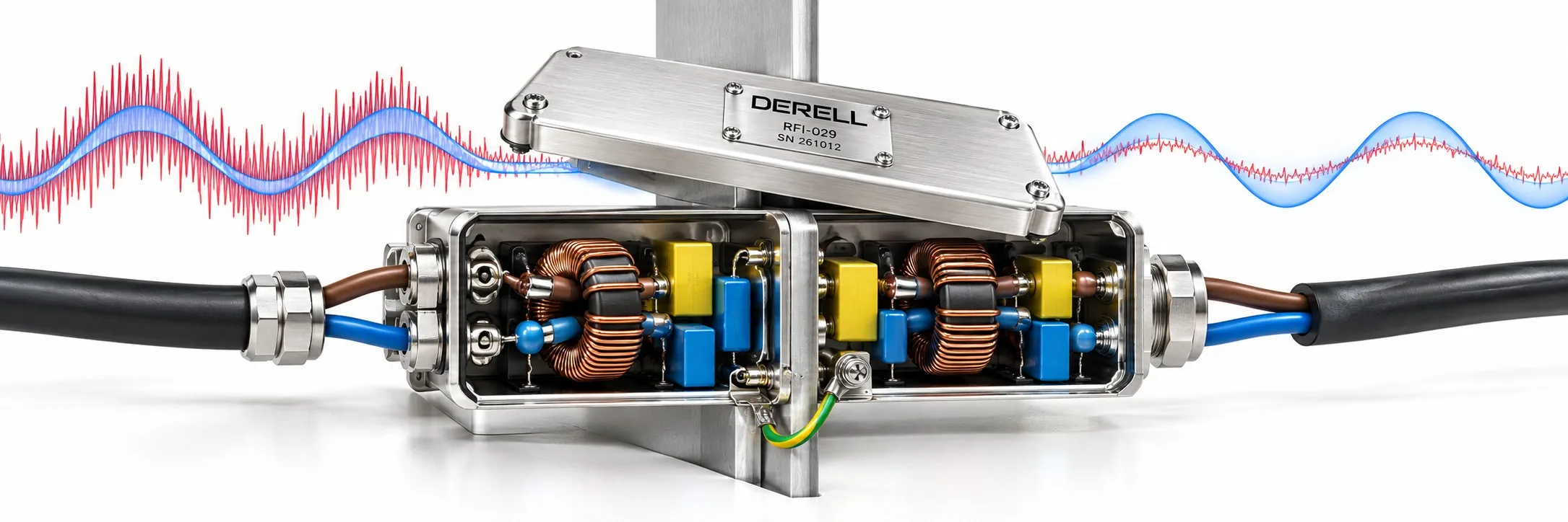
Keep unwanted RF energy off the connection
An RFI filter reduces radio-frequency interference. The term does not restrict its use to radio receivers: industrial controls, computers and power electronics can also suffer from RF disturbances. A power-line RFI filter mainly attenuates interference travelling along the supply connection. It can reduce noise entering equipment and noise leaving it.
EMI filters use the broader interference terminology, while EMC filters are named for the compatibility objective. Product names often overlap. There is no universal 10 kHz starting point for every RFI filter; use the specified frequency response and application requirements.
Identify the route before choosing the remedy
Conducted interference follows wiring. Radiated interference couples through electromagnetic fields, and cables can act as antennas. An electromagnetic filter may help, but shielding and cable layout still need attention. Understanding the noise mechanism prevents buying a filter for the wrong path.
Variable frequency drives switch power through PWM; switch-mode power supplies can also create disturbances. A drive's carrier frequency does not describe its entire noise spectrum: fast pulse edges produce higher-frequency content. The symptoms may appear as incorrect PLC input states, unstable sensor readings or lost encoder counts.
Two interference modes need different paths
Typical mains filters combine inductors and capacitors. Differential-mode noise circulates between conductors. Common-mode noise travels in the same direction on conductors and may return through chassis or stray capacitance. X capacitors connect across the lines; Y capacitors may connect lines to earth or chassis in an appropriate design. A common-mode choke adds impedance to the common-mode noise path.
Press Start to watch the rapid variations shrink on the right. The blue supply reference stays unchanged as the red combined waveform approaches it. Stop restores the static comparison. The three-second transition is a teaching device, not a real filter response time or a measured performance claim. Some residual noise remains.
Treat the ratings as a complete set
Check supply voltage, phase arrangement, equipment input current, temperature and leakage current. Use the manufacturer's overload and inrush data instead of adding the same percentage margin to every application. Read attenuation curves for the relevant interference mode. Catalogue test impedances may differ from the installed source and load, so verify performance in the actual system.
Capacitive earth current from Y capacitors can affect residual-current protection. If an RCD trips, investigate total leakage and protective-device suitability. Never disconnect PE to stop tripping.
Do not let wiring bypass the filter
LINE is the supply side; LOAD is the equipment side. Separate incoming and outgoing wiring and keep the filter-to-equipment connection short. Position the filter at the boundary where noise crosses into or out of the protected area, following the manufacturer's layout instructions. Provide broad conductive case bonding and proper protective earthing. Case bonding does not replace the required protective conductor.
Related reading
References
TE Connectivity / Corcom: RFI power-line filters; SCHURTER: Filter measurements; SCHURTER: Ratings and leakage current; MPE: Installation and bonding; TDK: Noise suppression principles.