
RTD Self-Heating and Lead Resistance Errors
Why a good RTD can still report the wrong temperature
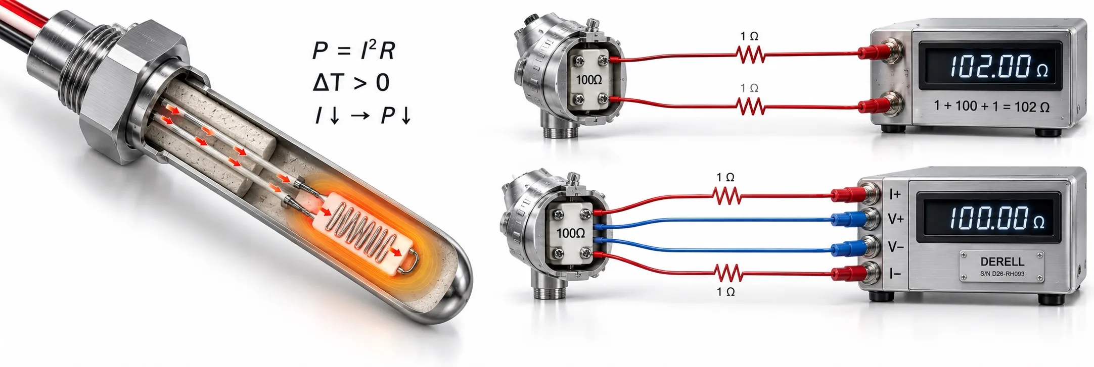
A Pt100 with a suitable tolerance class can still read high after installation. Two causes need different remedies: self-heating raises the sensing element’s temperature, while lead resistance makes the instrument measure extra resistance. One changes the sensor itself; the other changes the resistance attributed to it.
An RTD measurement applies an excitation current and measures voltage to determine resistance through Ohm’s law. That measurement supplies energy to the element, so the sensing process can influence the result.
Excitation current creates a thermal error
The element dissipates P = I² × R. With resistance unchanged, doubling the current produces four times the power. The resulting temperature rise depends on how effectively heat leaves the element. Flowing liquid, still air, the sheath and the mounting arrangement can produce different behaviour.
For a dissipation constant D in mW/°C, the approximate rise is ΔT = P / D. A self-heating coefficient in °C/mW is multiplied by power instead. Check the units: these two forms are reciprocals.
| Excitation | Element power | Approximate rise |
|---|---|---|
| 0.5 mA | 0.025 mW | 0.013 °C |
| 1 mA | 0.1 mW | 0.05 °C |
| 2 mA | 0.4 mW | 0.20 °C |
The dissipation constant here is an assumption for the calculation. Use data appropriate to the actual sensor and medium. A Pt100’s resistance increases with temperature, so constant-current excitation also produces more power at higher temperatures. Current selection must account for the manufacturer’s limits, noise and the measuring circuit’s operating range.
A two-wire connection includes both leads
In a two-wire RTD connection, the measured resistance is approximately Rmeasured = RRTD + Rlead1 + Rlead2. If each lead contributes 1 Ω, the total addition is 2 Ω. Using the Pt100’s average change of about 0.385 Ω/°C over 0–100 °C gives a quick error estimate of 2 / 0.385 = 5.2 °C.
For precise conversion, use the Callendar–Van Dusen relationship and the resistance slope at the relevant temperature. Reducing excitation current does not remove a two-wire lead-resistance error. Lead length, cross-section, temperature and connection resistance all matter.
What three and four wires actually improve
| Connection | Lead resistance | Self-heating |
|---|---|---|
| 2-wire | Both lead resistances are included in the measurement. | Can occur whenever measurement current flows. |
| 3-wire | A suitable input compensates matched lead resistances; imbalance can leave a residual error. | Is not cancelled by the third wire. |
| 4-wire | Separate current and voltage paths largely remove the lead contribution with a suitable high-impedance input. | Still depends on excitation and heat transfer. |
Three-wire compensation benefits from leads with matching length, material and cross-section. Unequal joints or contacts can upset that balance. Four-wire measurement does not eliminate every error source. Element tolerance, the reference resistor, electronics and mounting still affect temperature measurement accuracy.
Is Pt1000 a better choice for long leads?
The same 2 Ω addition gives about 0.52 °C of equivalent error for a Pt1000, using its average 3.85 Ω/°C change. But a Pt1000 dissipates more power at the same current: at 0 °C, 1 mA produces 0.1 mW in a Pt100 and 1 mW in a Pt1000. Compare excitation and thermal characteristics before drawing conclusions about self-heating.
Check the measurement chain before adjusting the reading
Confirm the input’s Pt100/Pt1000 selection and wiring mode first. A thermocouple, NTC or PTC setting uses a different conversion; Pt100s and thermocouples are not interchangeable without the correct input configuration. Long two-wire leads suggest a lead-resistance contribution. In a stable medium, comparing permitted excitation settings after thermal settling can help investigate self-heating.
For a multimeter resistance check, isolate the sensor from the measurement circuit according to the manufacturer’s procedure. Do not connect the meter’s current input across the RTD terminals. A suitable transmitter near the sensor can send 4–20 mA over the longer cable, but its accuracy and the receiving analogue input remain part of the error budget.