
what is hall effect?
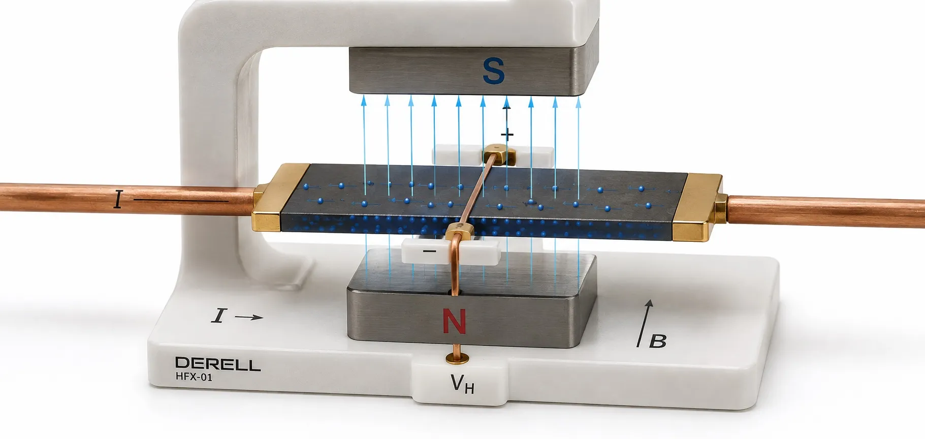
The physical principle that turns magnetic fields into measurable voltage
The Hall effect is the development of a Hall voltage across opposite sides of a current-carrying conductor or semiconductor when a suitably oriented magnetic field is applied. The field deflects charge carriers that are already moving through the material. The fundamental measured result is a transverse electrical potential difference.
Discovered by American physicist Edwin Hall in 1879, the effect is now used in current, position and speed measurement. The physical principle must be distinguished from the electrical characteristics of a complete sensor: the small voltage generated by the Hall element is processed electronically to produce a usable output.
How does the Hall voltage develop?
Electrons or other charge carriers moving through the material are deflected towards one side by the Lorentz force. Charge accumulating along the edges creates an electric field that opposes further deflection. At equilibrium, a voltage can be measured between those edges. The material does not have to be ferromagnetic; semiconductor Hall elements are widely used in sensors.
For a simple, uniform Hall plate, the relationship can be written as VH = RH × I × B⊥ / t. Here, I is the current through the plate, B⊥ is the magnetic flux density perpendicular to it, t is its thickness and RH is the material’s Hall coefficient. Magnetic flux density is expressed in tesla or millitesla. Reversing the field or current direction can reverse the Hall voltage polarity.
This equation describes an ideal bare Hall element. A complete sensor can have a different transfer characteristic because of amplification, offset, temperature compensation and its output circuitry. The Hall voltage and the sensor output voltage are therefore not necessarily the same quantity.
What does a Hall sensor detect, and what outputs are available?
A Hall sensor directly detects a particular component of a magnetic field. Position, speed or current is inferred through the arrangement of the magnet or conductor producing that field. A single-axis sensor has a sensitive direction that must be considered; multi-axis designs can measure more than one field component.
Linear Hall sensor: Its output changes with the sensed field within its measurement range. For models producing an analogue signal, the zero-field output depends on the device; some bidirectional models use approximately half the supply voltage. Zero magnetic field does not necessarily mean a 0 V output.
Hall switch: The output changes state when the field crosses an operating threshold and returns when it reaches a release threshold. The hysteresis between these thresholds reduces unstable switching near the transition point. A latch may require the opposite magnetic polarity to change state; moving the magnet away does not necessarily reset its output.
Complete devices can provide analogue voltage, switching, PWM or digital communication outputs. The distinction between analogue and digital inputs is therefore part of sensor selection. Sharing the same sensing principle does not make every Hall sensor suitable for the same control circuit.
Applications in current, speed and position measurement
Current measurement: Current flowing through a conductor produces a magnetic field around it. A Hall-based measurement arrangement detects that field to determine current; suitable designs can measure both DC and AC. An open-loop design evaluates the field directly, while a closed-loop design uses a compensating current to generate an opposing field. The difference between a Hall sensor and a conventional current transformer matters particularly for DC measurement.
Speed measurement: A magnet or multipole ring attached to a rotating shaft produces pulses as it passes the sensor. A suitable rotation monitoring system evaluates their frequency. If four pulses are generated per mechanical revolution and the measured frequency is 100 Hz, speed = 60 × 100 / 4 = 1500 rpm. Pulses per revolution, magnetic pole pairs and counted edges must not be confused.
Position and angle measurement: Movement of a magnet changes the field at the sensor. Suitable geometry and calibration allow linear position or rotation angle to be determined. Encoders use this information for motion feedback. However, a sensor with a linear field response does not automatically provide a linear measurement of the distance to its magnet.
Motor commutation: In some brushless electric motors, Hall sensors indicate the rotor’s electrical position and help the drive time its phase switching. This feedback is not necessarily equivalent to a high-resolution servo position measurement. Required angular resolution and the control method must be assessed separately.
What should be checked when connecting to a control system?
Supply and output compatibility: A sensor IC operating from 3.3 V or 5 V is not automatically suitable for direct connection to a 24 V PLC input. Check whether its output is open-collector, open-drain or push-pull, whether a pull-up is required, and the permitted voltage and current. For industrial products, NPN or PNP output compatibility with the controller input must also be verified.
Analogue scaling: Consider a hypothetical sensor with a 2.50 V zero-field output and a sensitivity of 20 mV/mT. Within its linear range, a +10 mT field would produce 2.70 V. The receiving analogue input must have a suitable range and resolution. These example values are not universal Hall sensor specifications; the individual product data sheet governs.
Speed and delay: Bandwidth, sampling rate and response time must suit the application. The controller must be able to capture the pulses produced by the sensor. In a fast rotating mechanism, standard input filtering or a long program cycle can cause pulses to be missed.
How does it differ from reed and inductive sensors?
A reed switch uses metal contacts moved by a magnetic field, whereas a Hall sensor uses a semiconductor sensing element. Hall sensing can eliminate mechanical contact wear, but supply and electronic output requirements still matter. An inductive proximity sensor typically detects how a metal target interacts with the field generated by the sensor itself. A Hall sensor should not be treated as a device that will necessarily detect any metal target without a magnet.
The conditions that determine measurement performance
Offset, temperature drift, linearity and noise must be assessed together. High resolution alone does not establish high accuracy. Changes in magnet strength with temperature, the air gap, assembly tolerances and nearby ferromagnetic parts can also affect the measurement.
High-current cables and busbars can add unwanted field components at the sensor. Electromagnetic interference and direct magnetic field interference should not be treated as an identical design problem: cable screening alone does not remove every magnetic influence. Layout, sensing direction and, where necessary, suitable magnetic shielding must be considered together.
A suitable Hall arrangement offers advantages such as contactless detection, static-field measurement and compact size. There is no universal sensing distance or accuracy figure, however. Selection between sensor technologies should follow target movement, environmental conditions, output interface and the required measurement performance.
Editor’s note: Explaining the Hall effect as “a magnet moving electrons to generate a current” is misleading. In the classical Hall arrangement, charge carriers in an already current-carrying material are deflected sideways, producing a transverse voltage. The bias current through the Hall element and the primary circuit current measured by a Hall current sensor are also separate quantities.
Related topics in Hall and magnetic sensing
Continue with Hall sensors, Hall-effect current sensors, Hall-effect encoders, optical versus magnetic encoders and Hall sensors versus reed switches.
Related control and measurement categories
For other parts of the application, explore PLCs and accessories, HMIs and operator panels, speed and current indicators, analogue signal controllers and, as a separate measurement topic, DC current transformers.
Return to the sensors category.
Sources
OpenStax: the physics of the Hall effect
Allegro MicroSystems: Hall-effect sensor technology
Texas Instruments: linear, switch and latch sensors
Melexis: Hall elements, signal conditioning and magnetic sensing
Melexis: motor commutation and position feedback
LEM: open-loop and closed-loop Hall current sensing
Infineon: offset, sensitivity and measurement errors
Allegro MicroSystems: external magnetic field interference in current sensing