
What is output reactor?
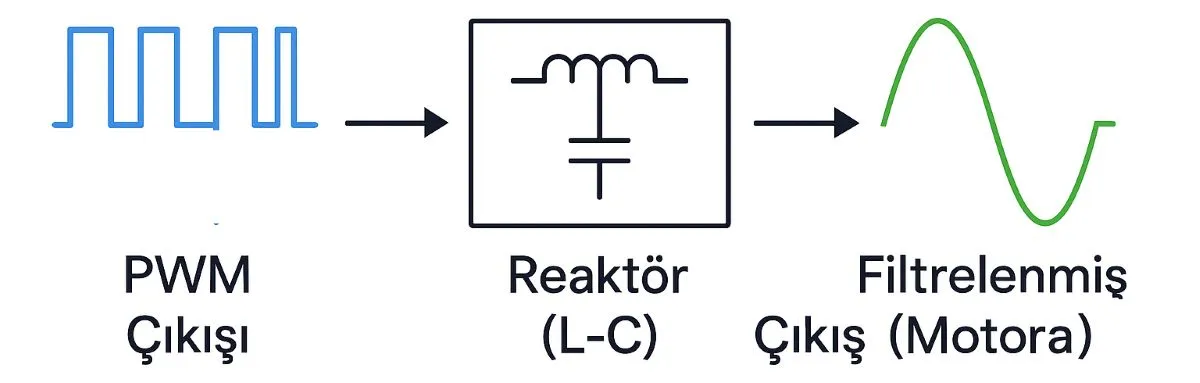
What the extra inductance does for your motor
An output reactor is an inductive component connected in series between the drive’s U/V/W terminals and the motor. A three-phase unit has a winding in each phase. It adds inductance to the motor circuit, limiting rapid changes in current and reducing switching-related current ripple. Its location and purpose differ from those of an input line reactor.
A variable frequency drive uses IGBT switches to generate PWM voltage pulses. Motor inductance already helps turn this pulsed excitation into a smoother current; the reactor adds to that effect. Smoother current does not mean sinusoidal voltage. A plain reactor leaves the voltage pulse shaped, an important distinction when choosing an output filter.
A simple way to understand the coil
vL = L × di/dt relates the voltage across an inductor to the rate at which its current changes. For the same inductor voltage, more inductance means a slower current change. Its ideal inductive reactance is XL = 2πfL, so reactance increases with frequency.
For an ideal 1 mH coil, this gives approximately 0.31 Ω at 50 Hz and 62.8 Ω at 10 kHz. These numbers illustrate the principle, not a complete reactor model: real cores have losses and parasitic effects. The drive’s switching frequency, also called its carrier frequency, must be distinguished from the fundamental output frequency that determines motor speed.
Compare voltage pulses with current ripple
The upper trace represents voltage; the two lower traces represent current. Start the moving time marker and compare the small zigzags at the same point in the cycle. Additional inductance reduces current ripple while the voltage remains pulsed. These traces are conceptual illustrations, not measurements, scaled waveforms or a prediction for a particular installation.
When a reactor is enough—and when it is not
A long motor cable introduces capacitance and can produce reflected voltage pulses. A suitable reactor can limit cable charging currents and moderate some transient effects. Where the motor requires a specified terminal peak voltage or voltage rise rate, choose a solution whose manufacturer confirms that performance. There is no universal cable length at which every drive needs the same reactor.
A dV/dt filter targets pulse rise rate and peak voltage. A sine-wave filter is designed to produce a substantially sinusoidal phase-to-phase motor voltage within its operating limits. Bearing currents and common-mode noise need their own assessment; a zero-phase reactor is a different device from a series reactor in the three motor phases.
Specify the operating conditions, not just the power
The rated power is only one selection input. Check motor current, overload duty, voltage class, inductance, fundamental frequency and switching frequency. As with drive selection, the load’s operating conditions matter. Confirm that the reactor is approved for PWM output service; an input reactor cannot automatically be substituted.
The coil also introduces voltage drop and heat. This deserves particular attention with high-frequency spindle drives, because inductive reactance rises with fundamental frequency. Excessive drop reduces the voltage available to the motor and can restrict torque. Follow the drive/filter instructions for V/f operation, vector control and motor autotuning, rather than assuming all parameter settings remain suitable.
Keep the different filtering jobs separate
An EMC filter addresses a different problem from a harmonic filter. A DC bus choke operates in the DC link. An output reactor does not replace a line-side solution for supply harmonics. Likewise, vibration or repeated drive faults does not establish that an output reactor is missing.