
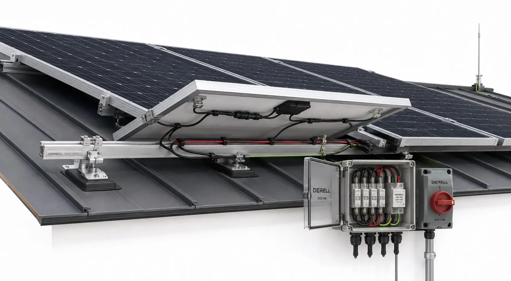
IEC 62548: Designing a PV Array That Stays Within Its Limits
IEC 62548-1 addresses the design of photovoltaic arrays, including DC wiring, protection, switching and earthing. It deals with safety issues arising from the way PV sources behave electrically.
A compliant solar module is only the starting point. Once modules are connected together, the resulting voltages, currents and possible fault paths must suit every component in the circuit. The array needs to be designed as a system.
Understand the Scope Before Applying It
The current scope includes the PV array and final power conversion equipment. It excludes storage devices, loads and the AC or DC distribution network supplying those loads, while adding array protection provisions for direct DC battery connections.
For projects involving solar energy storage, the battery and its associated safety requirements therefore need separate attention. IEC 62548-1 is also not an environmental impact assessment or a guarantee of annual energy yield. Structural design and local project approvals remain additional considerations.
Start with String Voltage and Array Current
Series and parallel connections change the electrical demands placed on the installation. Modules connected in series form a string: their voltages add. Connecting strings in parallel increases the combined current. Total array wattage alone cannot establish suitable equipment ratings.
Cold conditions raise open-circuit voltage. A string calculation must therefore consider the lowest expected cell temperature, the module’s voltage temperature coefficient and applicable tolerances. Multiplying the module’s standard-test-condition Voc by the number of modules can underestimate the maximum voltage.
Worked example: Assume a module has a Voc of 50 V at 25°C and a Voc temperature coefficient of −0.28%/°C. At a cell temperature of −10°C, a simplified correction gives 50 × [1 + 0.0028 × 35] = 54.9 V. Nineteen modules in series would reach approximately 1,043.1 V, exceeding a 1,000 V inverter DC input limit.
This example illustrates the temperature effect; it is not a completed string design. The final assessment must also check the modules, cable, connectors and switching equipment, together with the relevant design allowances.
Check the Operating Window, Not Just the Maximum Voltage
A solar inverter has several distinct input limits. Maximum DC voltage, operating current, permissible short-circuit current and the MPPT voltage range each need to be checked. Passing one check does not establish compatibility with the others.
Hot modules can have a lower operating voltage, making the lower end of the MPPT range relevant. Weather conditions therefore affect both output and electrical design. Where strings face different directions or experience different shading, their allocation to MPPT inputs should reflect the effects of shade and panel orientation.
Specify the Cable and the Connection
Cable selection involves voltage rating, current-carrying capacity, temperature rating and suitability for the installation environment. Hot roof surfaces, grouped circuits, installation method and mechanical exposure can all affect the choice.
Voltage drop is a separate calculation. A conductor may carry the current safely yet introduce excessive losses over a long route. Conversely, a generous conductor size does not establish that its insulation and environmental ratings are suitable.
Physical fit does not prove connector compatibility. Use matching connector types from the same manufacturer, with the specified cable and assembly tools. A generic “MC4-compatible” claim is insufficient justification for mixing brands. Poor mating or crimping can create a high-resistance connection even when the circuit current remains within its normal range.
Coordinate Overcurrent Protection and DC Switching
Parallel strings and other connected sources may feed reverse current into a faulted string. Whether protection is needed, and how it should be rated, depends on the available fault current, module limits, cable capacity and circuit arrangement. Installing the same fuse rating on every project is not a design method.
A PV fuse or circuit-breaker must have appropriate DC ratings and breaking capacity. Where gPV fuses are required, selection must coordinate with the module and conductor limits. An AC rating cannot be assumed to provide an equivalent DC interrupting rating.
Isolation and overcurrent protection serve different functions. Select a DC device suitable for the required isolation duty and, where applicable, load switching. PV connectors must not be used to interrupt load current. Stopping the inverter also does not remove voltage from illuminated modules or all array-side wiring.
Treat Earthing, Insulation Monitoring and Surge Protection Separately
Protective earthing and bonding of exposed metalwork is different from intentionally earthing a DC circuit conductor. Do not connect a PV pole to earth without checking the module and inverter architecture. Insulation monitoring and earth-fault detection must also suit that architecture.
The need for a surge protective device, and its selection, should consider the lightning protection arrangement, cable routes, system voltage and applicable installation requirements. Devices used on the array side need suitable PV/DC characteristics.
Mounting Details Still Matter
Approved clamp zones, support spacing, cable retention and mechanical loading should be checked against the manufacturer’s documentation. Assessing roof suitability also requires structural consideration. A sound electrical design does not establish that the roof can support the proposed installation.
Several standards contribute different pieces of evidence. IEC 61730 addresses module safety, IEC 61215 addresses module design qualification, and IEC 62109 addresses PV power converter safety. Product compliance supports the design process but does not replace the array calculations.
Make the Design Traceable
The project file should contain the applicable single-line diagram, equipment data, string calculations, cable selection, protection coordination, earthing arrangement and mounting details. The IEC 62446 series provides related requirements for documentation, verification and maintenance.
Keep those records available for later PV maintenance and equipment replacement. A change of module, inverter or string arrangement should be assessed against the design limits. A claim of IEC 62548 conformity needs supporting evidence; the standard number alone is not a whole-site certificate or permission to connect.