
Simatic S5 expansion modules
Siemens SIMATIC S5 Supplementary Modules and Accessories
The Siemens SIMATIC S5 supplementary modules category includes simulation equipment, operator panels, PG programming devices, CP 580/581 industrial PC components, memory and disk units, network hardware and mechanical accessories. These products support maintenance, program backup, troubleshooting, training and expansion of existing S5 installations with suitable hardware.
Select a part by its complete 6ES5 order number, function, hardware revision and host system. This category covers several product generations; inclusion here does not establish compatibility with every SIMATIC S5 CPU. Identify the existing S5 module arrangement and the required function first.
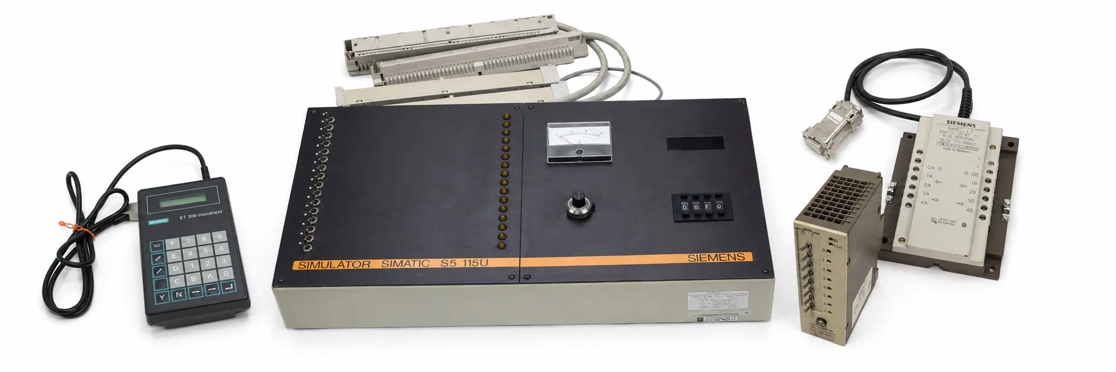
Simulators and training equipment
Digital and analog simulation: 6ES5 788-7LA11 · 6ES5 788-7LB11. The 7LA equipment is intended for binary-signal testing, while the 7LB equipment is for analog signals. Match the I/O board and connecting cable to the simulator’s own connection arrangement.
Other simulation equipment: 6ES5 788-0LC11 · 6ES5 788-8MA11 · 6ES5 788-8MK11. The 8MA11 is a digital I/O simulation module; the 8MK11 is used to simulate S5-90U/95U digital input signals. Check connectors and channel wiring as well as switch operation.
Operator panels and operating equipment
391 group: 6ES5 391-5AA12 · 6ES5 391-5AA13. OP 393 family: 6ES5 393-0UA11 · 6ES5 393-0UA12 · 6ES5 393-0UA13 · 6ES5 393-0UA15. OP 395 / OP 396: 6ES5 395-0UA11 · 6ES5 396-0UA11. This group includes panels, operating hardware and different hardware versions. Review the individual model page to establish what each order number includes.
When replacing a panel, assess the PLC connection, communication cable, keyboard/display arrangement and application data exchange together. Similar dimensions do not establish that the existing application will work with a replacement unchanged.
PG programming devices and accessories
PG 605U: 6ES5 605-0UA11 · 6ES5 605-0UA12. PG 615, PG 635, PG 675 and PG 685: 6ES5 615-0UA11 · 6ES5 635-0UA11 · 6ES5 675-0UA11 · 6ES5 685-0UA11. These devices are considered for working with existing S5 programs and maintenance tasks. Supported instructions, display/keyboard arrangements and storage methods depend on the model.
PG peripherals and programming accessories: 6ES5 685-1AA11 · 6ES5 685-3AA11 · 6ES5 686-4AA11 · 6ES5 695-0AA11. Distinguish graphics hardware, disk equipment and EPROM programming functions using the individual product description. Establish whether the supplied item is a complete device, an expansion or a peripheral.
STEP 5, parameter software and documentation
Programming documents and software/data media: 6ES5 815-0UA12 · 6ES5 816-0AA11 · 6ES5 885-0SA11 · 6ES5 894-0MA02-0UG4 · 6ES5 895-4SF11. Evaluate these separately from electronic boards. Check the document edition, software version, language, intended PG/PC, disk format and any licence documentation.
The STEP 5 version and a COM parameter package are separate considerations. A readable disk alone does not establish compatibility with the intended operating system or the required usage rights. Record the existing project files and software version, and create a readable backup without altering the original media.
CP 580 and CP 581 industrial PC hardware
CP 580: 6ES5 580-0UA11 · 6ES5 580-0UA12. CP 581 basic/processor modules: 6ES5 581-0EA11 · 6ES5 581-0EB11 · 6ES5 581-0EC12 · 6ES5 581-0ED12 · 6ES5 581-0ED13 · 6ES5 581-0ED14 · 6ES5 581-1EA11 · 6ES5 581-1EB11 · 6ES5 581-1EB12 · 6ES5 581-1EC12. These products provide PC functions associated with an S5 system. Their role must be distinguished from that of the standard PLC CPU.
CP 581 memory expansion: 6ES5 581-0HA11. AT slot hardware: 6ES5 581-0RA11 · 6ES5 581-0RA12. Match the processor version, memory arrangement, installed board and physical layout. A single RAM capacity or processor speed cannot be applied to every 581 component.
CP 581 mass-storage units: 6ES5 581-0LA11 · 6ES5 581-1LA11 · 6ES5 581-3LA11 · 6ES5 581-4LA11 · 6ES5 581-5LA11 · 6ES5 581-6LA11. Verify disk capacity and connections against the complete model. For a disk removed from a working system, preserving the operating system, application and machine-specific data is as important as checking the hardware.
Memory, disk and special control hardware
CP 513 / CP 516 memory hardware: 6ES5 513-3LA11 · 6ES5 516-3UA11. 550, CP 551 and CP 552 hardware: 6ES5 550-0DS11 · 6ES5 551-3UA11 · 6ES5 552-3UA21. Establish each item’s memory, disk or processing role from its complete order number. Assess the system slot, data exchange and required software together.
ICM 560: 6ES5 560-8AA11. Applying power alone does not fully test special control hardware. Verify the application connections, parameters and system data exchange. Also review S5 memory modules and S5 function modules for related options.
BT 777 SINEC L1 bus terminals
6ES5 777-0BB00 · 6ES5 777-0BB01 · 6ES5 777-0BC00 · 6ES5 777-0BC01 · 6ES5 777-1BC00 · 6ES5 777-1BC01. BT 777 bus terminals are SINEC L1 network components. Assess cable length, connecting lead, isolation and mounting for the specific version. Distance or cable details for one model must not be applied to every 777 order number.
When investigating a communication fault, check network end connections, cable continuity, shielding and connected stations together. System-side options can be found under S5 communication modules.
SINEC H1, Ethernet and ET 200 connection hardware
SINEC H1 transceiver and connection hardware: 6ES5 755-0AA13 · 6ES5 755-1AA12. ET 200 bus termination component: 6ES5 755-2CA11. Industrial Ethernet terminators and coaxial connector: 6ES5 755-3AA11 · 6ES5 755-4AA11. Match the network type, cable and connector standard using the complete code.
ET 200 handheld: 6ES5 782-2MB11. It is used for commissioning and diagnostics with supported ET 200/SINEC L2-DP stations. Available functions depend on the connected station. Other protocol/remote-operation hardware: 6ES5 757-0AA11 · 6ES5 758-0AA11. SINEC L1, L2-DP and H1 components must not be assumed to use the same connection standard.
Special I/O, comparator and electronic terminal-strip hardware
400 group input/timing hardware: 6ES5 400-0AA11 · 6ES5 400-7AA11 · 6ES5 400-7AA12. ET 200B electronic module: 6ES5 431-2BA11. Check signal voltage, channel function and system connections for the individual model. A single input count cannot be assigned to the entire 400 family.
Two-channel comparator: 6ES5 461-8MA11. It evaluates analog signals against adjusted thresholds and has a different function from a standard analog measurement board. EKL 484 electronic terminal-strip hardware: 6ES5 484-8AB11 · 6ES5 484-8AC11. EKL 484 is a field I/O connection system; it is not selected as a network terminating resistor.
488 group I/O hardware: 6ES5 488-3LA11. 763 group supplementary hardware: 6ES5 763-7LA11. Check the label, connector and system diagram together for these legacy products. Depending on the function, also review digital input, digital output, combined I/O and analog module options.
776 power output modules
6ES5 776-7LA11 · 6ES5 776-7LA12-Z · 6ES5 776-7LA13. 776 power output modules control suitable AC loads. Their function differs from that of a power supply. Verify load voltage, channel current, total loading, cooling and the version-specific control method in the appropriate manual.
For resistive-load applications in particular, an unloaded output check is insufficient. Assess switching and temperature rise under a suitable load. S5 power supplies for supplying the PLC are listed separately.
Adapter casings, racks and mechanical parts
491 adapter casings: 6ES5 491-0LA11 · 6ES5 491-0LB11 · 6ES5 491-0LC11 · 6ES5 491-0LD11. Other rack, holder and terminal hardware: 6ES5 710-0AB21 · 6ES5 740-0AA11 · 6ES5 741-0AB31. Jumper module: 6ES5 756-0AA11. These parts complete the mechanical or connection arrangement and must be matched to the board, slot and system diagram.
Other programming/interface hardware: 6ES5 500-7AA11 · 6ES5 512-5BU12. Check the connection type at both ends and the required cable when selecting an interface. Review related S5 interface modules, cables and connectors and mounting racks as part of the complete system.
Used equipment purchasing and selling
For a quotation, provide the complete model, quantity, working or faulty condition, label photograph, included accessories and asking price. Send details of equipment you wish to sell to otomasyonavm@gmail.com. Sales require an invoice; used equipment is sold without returns. Workshop testing may be arranged when a suitable system and connection hardware are available.
Editor's Note
Establish what the part actually does first. A 6ES5 number does not make it suitable for every S5 system. Read the complete label and identify the host equipment and connectors together.
For an old PG or CP 581, go beyond a successful power-up. Check disk access, application startup and a real PLC connection. Preserve a readable backup of working machine data before making changes; do not format the disk simply to test it.
A few working simulator switches do not prove that every channel is healthy. Test the required channels individually and include the cable and connector. A missing adapter cable can prevent otherwise sound equipment from being used.
A bus terminal, terminating resistor and transceiver perform different functions. Identify the network and cable type before choosing a replacement. A connector fitting mechanically does not establish communication compatibility.
Test panel keys, the display and PLC data exchange together. For a CP system, assess the main board with its disk, memory and slot hardware. Finding missing accessories later can be harder than finding the main device.
Keep power output modules distinct from power supplies. Identify the label and the correct manual before connecting a load. A controlled test with an appropriate load reveals much more than an LED check.
OtomasyonAVM Resources and PDF Manuals
+ Shared Siemens SIMATIC S5 PDF archive
+ SIMATIC S5 ST 50 catalogue, 1998 — English
+ SIMATIC S5 ST 53 catalogue, 1985 — German
+ CP 581 user manual — English
+ ET 200 handheld manual — English
+ SINEC L1 / CP 530 manual — English
Related Topics
S5 memory modules · S5 communication modules · S5 interface modules · S5 function modules
Browse SIMATIC S5
Parent S5 module category · SIMATIC S5 CPU options · Siemens S5 PLCs · Used Siemens automation equipment
Siemens and External References
+ S5-100U System Manual (English)
+ CP 580 Documentation Supplement (English)
+ SINEC L1 / CP 530 Manual (English)
Refine Search
- 6ES5 391-5AA12
- 6ES5 391-5AA13
- 6ES5 393-0UA11
- 6ES5 393-0UA12
- 6ES5 393-0UA13
- 6ES5 393-0UA15
- 6ES5 395-0UA11
- 6ES5 396-0UA11
- 6ES5 400-0AA11
- 6ES5 400-7AA11
- 6ES5 400-7AA12
- 6ES5 431-2BA11
- 6ES5 461-8MA11
- 6ES5 484-8AB11
- 6ES5 484-8AC11
- 6ES5 488-3LA11
- 6ES5 491-0LA11
- 6ES5 491-0LB11
- 6ES5 491-0LC11
- 6ES5 491-0LD11
- 6ES5 500-7AA11
- 6ES5 512-5BU12
- 6ES5 513-3LA11
- 6ES5 516-3UA11
- 6ES5 550-0DS11
- 6ES5 551-3UA11
- 6ES5 552-3UA21
- 6ES5 560-8AA11
- 6ES5 580-0UA11
- 6ES5 580-0UA12
- 6ES5 581-0EA11
- 6ES5 581-0EB11
- 6ES5 581-0EC12
- 6ES5 581-0ED12
- 6ES5 581-0ED13
- 6ES5 581-0ED14
- 6ES5 581-0HA11
- 6ES5 581-0LA11
- 6ES5 581-0RA11
- 6ES5 581-0RA12
- 6ES5 581-1EA11
- 6ES5 581-1EB11
- 6ES5 581-1EB12
- 6ES5 581-1EC12
- 6ES5 581-1LA11
- 6ES5 581-3LA11
- 6ES5 581-4LA11
- 6ES5 581-5LA11
- 6ES5 581-6LA11
- 6ES5 605-0UA11
- 6ES5 605-0UA12
- 6ES5 615-0UA11
- 6ES5 635-0UA11
- 6ES5 675-0UA11
- 6ES5 685-0UA11
- 6ES5 685-1AA11
- 6ES5 685-3AA11
- 6ES5 686-4AA11
- 6ES5 695-0AA11
- 6ES5 710-0AB21
- 6ES5 740-0AA11
- 6ES5 741-0AB31
- 6ES5 755-0AA13
- 6ES5 755-1AA12
- 6ES5 755-2CA11
- 6ES5 755-3AA11
- 6ES5 755-4AA11
- 6ES5 756-0AA11
- 6ES5 757-0AA11
- 6ES5 758-0AA11
- 6ES5 763-7LA11
- 6ES5 776-7LA11
- 6ES5 776-7LA12-Z
- 6ES5 776-7LA13
- 6ES5 777-0BB00
- 6ES5 777-0BB01
- 6ES5 777-0BC00
- 6ES5 777-0BC01
- 6ES5 777-1BC00
- 6ES5 777-1BC01
- 6ES5 782-2MB11
- 6ES5 788-0LC11
- 6ES5 788-7LA11
- 6ES5 788-7LB11
- 6ES5 788-8MA11
- 6ES5 788-8MK11
- 6ES5 815-0UA12
- 6ES5 816-0AA11
- 6ES5 885-0SA11
- 6ES5 894-0MA02-0UG4
- 6ES5 895-4SF11