
PID Control with PLC
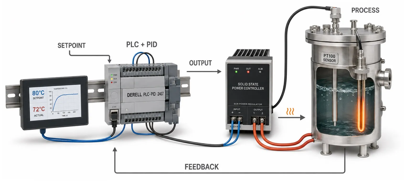
What is PID control with a PLC? PID control in a PLC calculates a command for a pump, valve or heater to bring a measured process value towards its target. The PID controller evaluates feedback, while the PLC program manages operating permissions, sequences and faults. PID is one control function within the machine's overall program.
Where is it used? Temperature, pressure, flow and level control are typical applications. The controller may adjust furnace heating power, pump speed or a tank valve's opening. The controlled quantity differs from the manipulated quantity; in pressure control, pressure is the target variable while the changing command may be a pump speed reference.
What do SP, PV and MV mean? SP is the setpoint, PV the measured process value, and MV the manipulated variable applied to the process. A sensor provides PID feedback. Setpoint and measurement must use matching units and scales; a target in bar cannot be compared directly with raw analogue counts.
Calculating the error: A common convention is error = SP − PV. A 6 bar setpoint and a 5 bar measurement give an error of +1 bar. PID operation considers this difference and its behaviour over time. A +1 bar error does not automatically correspond to a particular output percentage or frequency; the result depends on the settings and control direction.
P — Proportional action: Among the PID components, P produces a correction based on the current error. Increasing gain creates a stronger response to the same error. Excessive gain can cause oscillation, while insufficient gain can produce a slow response. With proportional action alone, some processes retain a steady difference between setpoint and measurement.
I — Integral action: I responds to error accumulated over time, aiming to remove a persistent offset. If temperature remains slightly below target, for example, the command can increase over time. Overly aggressive integral action can cause overshoot and oscillation; reaching the target also depends on the equipment having enough capacity.
D — Derivative action: D responds to the rate of change of error or measurement, depending on the block's structure. Suitable settings can help damp rapid changes. D does not measure the future or guarantee that overshoot will be prevented. Because it can amplify measurement noise, filtering and sensor quality matter.
Are all three actions necessary? The choice of control strategy depends on process behaviour. PI control may be sufficient for applications such as pressure and flow; adding derivative action does not always improve performance. The appropriate structure is the one that achieves the required stability and response, regardless of how many terms it contains.
Scaling the analogue measurement: A 4–20 mA or 0–10 V signal is converted into engineering units. For an ideal linear 0–10 bar / 4–20 mA measurement, 12 mA represents 5 bar. The raw count range of the analogue signal depends on the module. Evaluate broken wires, out-of-range readings and sensor faults separately; do not treat a faulty measurement as a valid PV.
Hardware and the signal path: Consider the pressure sensor, I/O module and any remote I/O together. Measurement range, resolution, filtering and update time affect control behaviour. Adjusting P/I/D parameters cannot correct an incorrectly wired or incorrectly scaled measurement.
Running the PID block regularly: Task scheduling in the PLC CPU determines the block's call interval. Sampling must suit the process dynamics, and the block's timing settings must match its actual execution. Some blocks distinguish the call interval from the PID calculation interval. Calling the block on every PLC scan, or using one interval for every process, is not a universal rule.
Function blocks and parameter conventions: A function block provided by the programming software can be used; check the inputs, modes and limits of its specific version. Environments including CODESYS may use Kp/Ki/Kd or Kp/Ti/Td conventions. Integral gain and integral time are different parameters; verify units and algorithm structure before transferring values between blocks.
Checking control direction: Low pressure generally requires a higher pump speed, while excessive temperature requires less heating. Verify how changing the output affects the process. An incorrect direction increases the error instead of reducing it. Check the meaning of direct/reverse action and gain sign in the chosen block's documentation.
The PID output is not motor power: The calculated value can be sent to a variable frequency drive as an analogue or communication reference. Configure the frequency range represented by a 0–100% command. With a linear 0–100% = 20–50 Hz mapping, for example, 40% represents 32 Hz. The drive's own PID function is another option; avoid conflicting independent loops acting on the same reference, and design cascade control separately.
Output limits and integral windup: Error can persist when a valve is fully open or a pump has reached its speed limit. Excessive integral accumulation is called windup and can delay recovery. When considering PID limitations, assess anti-windup and the actual actuator limits. Clipping the final output alone does not prevent internal integral accumulation in every implementation.
Control and automatic tuning are different: PID settings depend on delays and process dynamics. During normal operation, PID calculates the output; it need not adjust its own gains. Automatic tuning, where available, is a separate operation. It can change the output and process value, so establish test conditions and permitted limits beforehand.
Manual/automatic transfer and monitoring: An HMI can provide setpoints and manual output commands; SCADA can display trends. Record SP, PV, output and operating mode together. In PID applications with SCADA, identify which device actually executes the controller. Configure output tracking or bumpless transfer, where supported, to reduce output jumps when switching from manual to automatic operation.
Multiple-pump applications: In pump control, PID can regulate pressure while PFC and pump duty rotation manage which pumps run and when. PID tuning, pump sequencing and operating-hour balancing are separate tasks. Assess the sudden capacity change when another pump starts alongside the transition logic.
Commissioning and troubleshooting: During PLC debugging, first check measurement accuracy, control direction, operating permissions and actual equipment response. When investigating PID problems, establish whether oscillation comes from tuning, sensor noise or a sticking valve. Define the response to sensor faults, communication loss and power restoration separately.